TM 5-3895-383-24
Oil is supplied to the drum drive motor by the drum propel
pump. The direction of the motor rotation is controlled by the
oil flow direction from the propel pump. The displacement and
the speed are controlled by the shift valve.
The components of the drum drive motor that rotate are drive
shaft (1), retainer (3), pistons (4), and barrel (6). The
components of the drum drive motor that do not rotate are
motor case (2), head (8), and control lens (14). Spring (5)
pushes barrel (6) against control lens (14). This makes a high
pressure seal between the barrel and the control lens. A seal
is also made between the control lens and the head.
When high pressure oil flows through the high pressure loop
line, the oil also flows to control slot (15). Oil in the control slot
goes into the cylinders of barrel (6) that are over the control
slot.
The spherical piston heads are held in the sockets in drive
shaft (1) by retainer (3). Seven pistons (4) are held by barrel
(6). The barrel rotates around pivot pin (17) which is at an
angle to the axis of the drive shaft (1). The design of the bent
axis between the barrel and the shaft causes each piston to
move. The pistons, the barrel, and the drive shaft rotate as
pressure oil enters the cylinders.
The pistons are fully retracted when the pistons are in the top
center position. The cylinder overlaps control slot (15) on the
low pressure side of the loop at this point. When the piston
starts to move down, the oil is pushed out of the cylinder. The
oil also moves out of the control slot, the other high pressure
loop port and exits to the low pressure side of the loop.
The drum drive motor is lubricated by oil leakage from the
pistons and the barrel.
The drum drive motor operates at either a large displacement
or at a small displacement. When the propel motor operates at
a large displacement, the barrel and the shaft are at the
maximum angle. At this point the barrel and the shaft are
against the maximum displacement adjustment screw (13).
When the propel motor operates at a small displacement, the
barrel and the control lens are at the minimum angle against
minimum displacement adjustment screw (7).
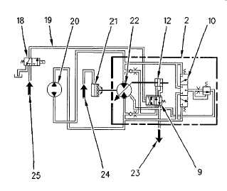
Illustration 51
Hydraulic Schematic for the Drum Drive Motor
(2) Motor case. (9) Valve spool. (10) Flushing valve. (12)
Control piston. (18) Shift valve. (19) Cavity for pilot oil. (20)
Drum propel pump. (21) Drum brake. (22) Drum drive motor.
(23) Line to thermal bypass valve. (24) Line from charge
circuit. (25) Line from charge circuit.
The cavity for pilot oil (19) does not receive control pressure
when the propel motor is in LOW speed. When the valve spool
(22) is shifted to the left, high pressure oil flows to the left side
of control piston (12). At this point, the control lens (14) and
the barrel are held at the maximum displacement angle.
The cavity for pilot oil (19) receives control pressure when the
propel motor is in HIGH speed. When the valve spool (9) is
shifted to the right, high pressure oil flows to the right side of
control piston (12). At this point the control lens (14) and the
barrel are held at the minimum displacement angle.
10-46