TM 5-3895-383-24
Control Valve
SMCS Code: 5051; 5261
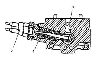
Illustration 31
Directional Control Valve
(1) Lever. (2) Spool. (3) Passage for charge oil. (4) Control
valve body. (5) Servo valve lever.
The propel control lever delivers a mechanical input to lever
(1). This input determines the amount that spool (2) is rotated.
The output of the propel pump is proportional from 0 to 100
percent. This is based on the amount of charge oil that is
allowed to flow from passage (3) through spool (2) and into the
servo valve. Charge oil flows through passage (3) to the spool
(2) and the oil is sent to either the right end of the servo valve
or left end of the servo valve. The charge oil pressure shifts
the servo valve, and a mechanical signal is sent to the
swashplate. This upstrokes the propel pump.
Neutral Start Control
SMCS Code: 7459; 7499
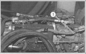
Illustration 32
Location of Neutral Start Switch on Propel Pump
(1) Neutral start switch.
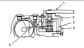
Illustration 33
Neutral Start Switch
(2) Spool. (3) Electrical Switch. (4) Neutral art switch pin.
When the control valve spool (2) is centered properly, neutral
start switch pin (4) will rest between the spool and electrical
switch (3) The electrical contact for the starter relay will not be
broken. If spool (2) is shifted from neutral, pin (4) will be
pushed outward. This will cause the contact inside electrical
switch (3) to open. When this happens the electrical continuity
of the start circuit will be broken and the machine will be
prevented from starting.
10-36