TM 5-3895-383-24
When properly positioned, locating pin (C) and bolt (B) on
timing fixture (2) will engage holes in top face of inlet manifold
(8). Tighten bolt (B) to secure timing fixture (2) firmly to inlet
manifold (8).
Slowly lower collet sleeve (A) until the long pin of timing fixture
(2) contacts shoulder (7) of the injector.
NOTE:
The sliding locating pin (C) and two hole positions
for bolt (B) are provided in the timing fixture
because of a different valve cover bolt hole
position on the rear cylinder.
10.
The digital dial indicator will display the Fuel Timing
Dimension directly, for example 63.00 mm will be
displayed as 63.00 mm and 63.50 mm will be displayed
as 63.50 mm.
Refer to the TMI (Technical Marketing Information) Governor
Bench Performance Data for the correct Fuel Timing
Dimension to use.
The digital dial indicator must show the correct Fuel Timing
Dimension within ± 0.20 mm. Each injector must be checked
separately, and adjusted if necessary.
11.
If the digital dial indicator displays the correct dimension
or is within the ± 0.20 mm checking tolerance, no
adjustment is necessary, proceed to step 14.
12.
If the dial indicator points do not indicate 0.00 ± 0.20
mm, loosen the locknut on push rod adjustment screw
(6) for the injector to be adjusted.
13.
Turn the adjustment screw (6) until the digital dial
indicator displays the correct Fuel Timing Dimension.
Tighten the locknut on the adjustment screw (6) to a
torque of 33 ± 7 N m (24 5 lb-ft) and check adjustment
again. If necessary, do this procedure again until the
adjustment is correct.
NOTE:
After timing fixture (2) has been installed on the
inlet manifold, do not rotate the engine. The
timing fixture may be damaged.
14.
The Fuel Timing Dimension can be checked or adjusted
on hall of the cylinders with the timing bolt installed.
Then, the timing bolt and the timing fixture must be
removed. Only then may the flywheel be rotated
counterclockwise 360 degrees (1 revolution), the timing
bolt and the timing fixture reinstalled to check Fuel
Timing Dimension on the remaining cylinders. Refer to
chart Crankshaft Positions For Fuel Timing.
15.
Remove the timing bolt from the flywheel when the Fuel
Timing Check is completed.
Engine Speed Measurement
Tools Needed
1U6602
Tachometer Group (Hand Held)
1
or
6V3121
Multitach Group
1
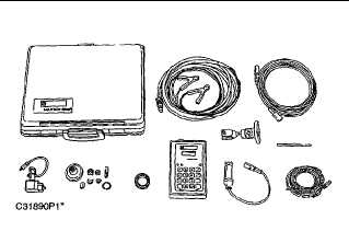
6V3121 Multitach Group
The 6V3121 Multitach Group can measure engine speed from
a magnetic pickup on the flywheel housing. It also has the
ability to measure engine speed from visual engine parts in
rotation.
Special Instruction, SEHS7807 is with the 6V3121 Multitach
Group and gives instructions for the test procedure.
The 1U6602 Tachometer Group is a phototach for general use.
The 1U6602 Tachometer Group is a phototach only and reads
only the basic input frequency (1 pulse per revolution per piece
of reflective tape) on any visible rotating part. The 1U6602
Tachometer Group does not replace the 6V3121 Multitach
Group.
Special Instruction, SEHS8854 is with the 1U6602 Tachometer
Group and gives instructions for its use.
6-75


