TM 5-3895-383-24
3126 Engine
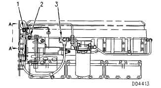
3126 Cylinder And Valve Location
Bore ...............................110.025 0.025 mm (4.3317 .0010 in)
Stroke .........................................................................27 mm (5.0 in)
Displacement ..................................................... 72 liter (450 cu in)
Number Of Cylinders .................................................................... . 6
Cylinder Arrangement..............................................................in-line
Valves per Cylinder ......................................................................... 2
Valve Lash Setting
Intake........................................................................ 38 mm (.015 in)
Exhaust ................................................................0.64 mm (.025 in)
Type of Combustion ................................................Direct Injection
Firing Order:.................................................................... 1-5-3-6-2-4
Direction of Crankshaft Rotation
(as viewed from flywheel end) ...........................counterclockwise
NOTE:
Front end of engine is opposite the flywheel end.
Left side and right side of engine are as viewed
from flywheel end. No. 1 cylinder is the front
cylinder.
Fuel Filter Lines Group
As Viewed From Left Side Of Engine.
As Viewed From Front Of Engine.
(1)
Fuel outlet port (return to tank).
(2)
Fuel inlet port.
(3)
Connector.
(4)
Cylinder head.
(5)
Drilled passage.
(6)
Tube assembly (fuel return to tank).
(7)
Tube assembly (fuel transfer pump to fuel filter).
(8)
Check valve assembly (maintains minimum fuel
system pressure and prevents fuel siphoning).
Minimum at low idle ............................... 50 kPa (7.2 psi)
NOTE:
Refer to the Testing and Adjusting Section of this
Service Manual, for the procedure to check the
fuel pressure.
(9)
Screen assembly (if equipped).
(10)
Pressure relief valve.
(11)
Fuel gallery.
5-5


