TM 5-3895-382-24
Systems Operation
Introduction
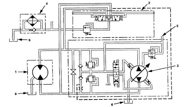
Vibratory System Schematic.
(1) Vibratory motor. (2) Vibratory flushing manifold. (3) Vibratory pump. (4) Hydraulic oil cooler. (5) Charge pressure line from the brakeshift valve.
(6) Hydraulic oil tank.
The vibratory system hydraulics let the operator control the
vibratory action of the drum. The drum is made to vibrate by
the rotation of an eccentric weight shaft inside the drum. The
weight shaft is coupled to vibratory motor (1), which rotates the
weight shaft rapidly, causing the drum to vibrate.
Vibratory motor (1) is a par of a closed-loop hydraulic system,
powered by vibratory pump (3). The vibratory pump is
mounted to the back of the tandem propel pumps. The
vibratory pump is a variable-displacement piston pump which
provides minimum pressure to the system when the vibratory
system is not operating. When not operating, the pressure of
the oil in the system will be 1655 to 2140 kPa (250 to 310 psi).
The operator controls the vibratory system operation, using the
vibratory control switch on the operators console. By moving
this switch, the operator controls the flow of oil through the
vibratory system.
The operator controls the direction of system oil flow (high or
low amplitude), determining the rotational direction of the
eccentric weight shaft. The construction of the weight shaft
causes the drum to vibrate in high-amplitude when the shaft is
rotated in clockwise direction, and in low-amplitude when
rotated in the counterclockwise direction.
If equipped with the variable frequency option, the operator
also can vary the quantity of system oil flow, determining the
frequency (in vibrations per minute) of the drum. Normal
operating range while propelling for the vibratory system is
approximately 1400 to 1800 vpm.
13-4


