TM 5-3895-382-24
3.
Remove the piston pin bearing from the connecting rod.
Install a new bearing in the connecting rod. The new
bearing is partially finished. The new bearing must be
bored off-center to the correct diameter. This off-center
position is determined by the grade of length of the
connecting rod. Refer to Table 22. The correct
diameter of the bore in the piston pin bearing is given in
the Specifications, "Connecting Rod" manual.
Surface finish of the bored hole in the piston pin
bearing .....................................Ra 0.8 micrometers
4.
Machine the ends of the piston pin to the correct length.
Remove any sharp edges. Refer to Specifications,
"Connecting Rod".
5.
If the grade of length of the connecting rod is changed,
the letter that is stamped on the connecting rod must be
removed. Etch a letter that is for the new grade of
length on the side of the connecting rod.
NOTE: Do not stamp a new letter on the connecting rod.
The
force
of
stamping
may
damage
the
connecting rod.
Table 22 references the following information: grade of
length of the connecting rod and lengths of the
connecting rods.
Table 22
Length Of The
Grade of
Color
Connecting
Length
Rod (CRL)
"F”
Red
165.728 to
165.761 mm
(6.5247 to
(6.5265 inch)
"G"
Orange
165.682 to
165.715 mm
(6.5229 to
(6.5247 inch)
"H"
White
165.637 to
165.670 mm
(6.211 to
(6.5229 inch)
“J"
Green
165.591 to
165.624 mm
(6.5193 to
6.5211 inch)
“K"
Purple
165.545 to
165.578 mm
(6.5175 to
6.5193 inch)
"L”
Blue
165.499 to
165.532 mm
(6.5157 to
6.5175 inch)
Measure The Length Of A Connecting Rod
If the mark or the color of the grade of length cannot be
observed on the connecting rod, perform the following
procedure:
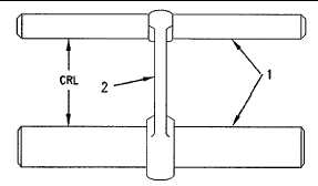
Illustration 88
Measure the length of the connecting rod.
(1) Measuring pins
(2) Connecting rod
(CRL) Connecting Rod Length
6-90