
TM 5-3895-379-23
PROPEL AND VIBRATORY VALVE TESTS AND ADJUSTMENTS - CONTINUED
0184 00
STABILIZED CONTROL VALVE SPOOL NEUTRAL ADJUSTMENT - CONTINUED
6.
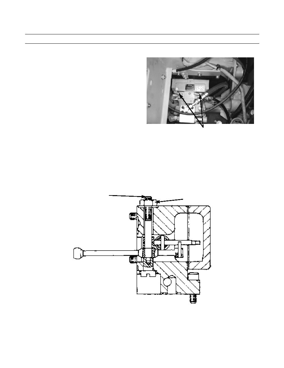
Remove two fittings (31) and plug ports (32).
7.
Remove plugs (22) and install connectors for pres-
sure gauges at ports (32).
8.
Install two 600 psi (4000 kPa) pressure gauges to
pressure taps (8) and (9).
9.
Set the propel control lever to HIGH SPEED posi-
tion (TM 5-3895-379-10).
NOTE
Both test gauges should show identi-
cal readings.
401-2150
If the readings are not equal, the
31,32
valve must be adjusted.
10.
Start and run the engine at 1500 rpm (TM 5-3895-
379-10).
NOTE
One-half revolution of adjustment screw gives all adjustment possible. Small movement of screw makes
a large difference in pressure.
11.
To adjust:
a.
Loosen lock nut (33) and turn adjustment screw (34) clockwise or counterclockwise to get equal pressures at
the gauges.
b.
Tighten lock nut (33) on adjustment screw (34).
34
33
401-2153
12.
Remove two stabilized control valve end covers (26).
13.
Remove two pistons (27) from two stabilized control valve end convers (26).
14.
Install springs (28) and shim (29) back into original locations.
15.
Assemble two stabilzed control valve end covers (26) and install on control valve body (30).
0184 00-7
