
TM 5-3895-379-23
SEAT SUSPENSION REPAIR - CONTINUED
0135 00
ASSEMBLY - CONTINUED
32.
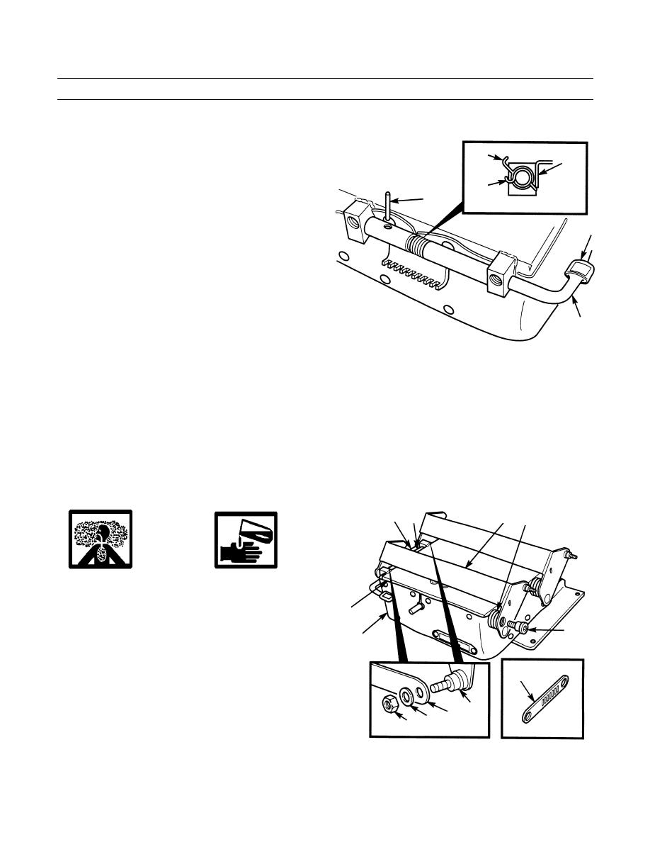
Install cap (22) on height adjustment lever (1).
19
21
33.
Install spring (20), latch assembly (19) and height
adjustment lever (1) in upper housing assembly (21).
20
34.
Install spring pin (18) in latch assembly (19) and
18
height adjustment lever (1).
CROSS-SECTION VIEW
22
1
401-716
35.
Position link (14) on link (11) on right-side of seat suspension assembly (15) ensuring that hole is fully seated on shoul-
der of stud.
36.
Apply sealing compound to threads of locknut (12).
37.
Install link (14) on link (11) with washer (13) and new locknut (12).
38.
Position link (14) on fingers of latch assembly (19).
39.
Position torsion spring (16) and link (11) on upper housing assembly (21).
40.
Install ends of torsion spring (16) in left-side of upper housing assembly (21) and link (11).
14
11 16
19
WARNING
Adhesives, solvents and sealing com-
pounds can burn easily, can give off
harmful vapors and are harmful to skin
21
and clothing. To avoid injury or death,
17
keep away from open fire and use in a
15
well-ventilated area. If adhesive, solvent
or retaining compound gets on skin or
REAR
clothing, wash immediately with soap
14
and water.
11
41.
Apply sealing compound to threads of bolts (17).
13 14
12
FRONT
42.
Install torsion spring (16) and link (11) on upper hous-
ing assembly (21) with two bolts (17), using socket
401-717
wrench screwdriver attachment.
0135 00-13
