
TM 5-3895-379-23
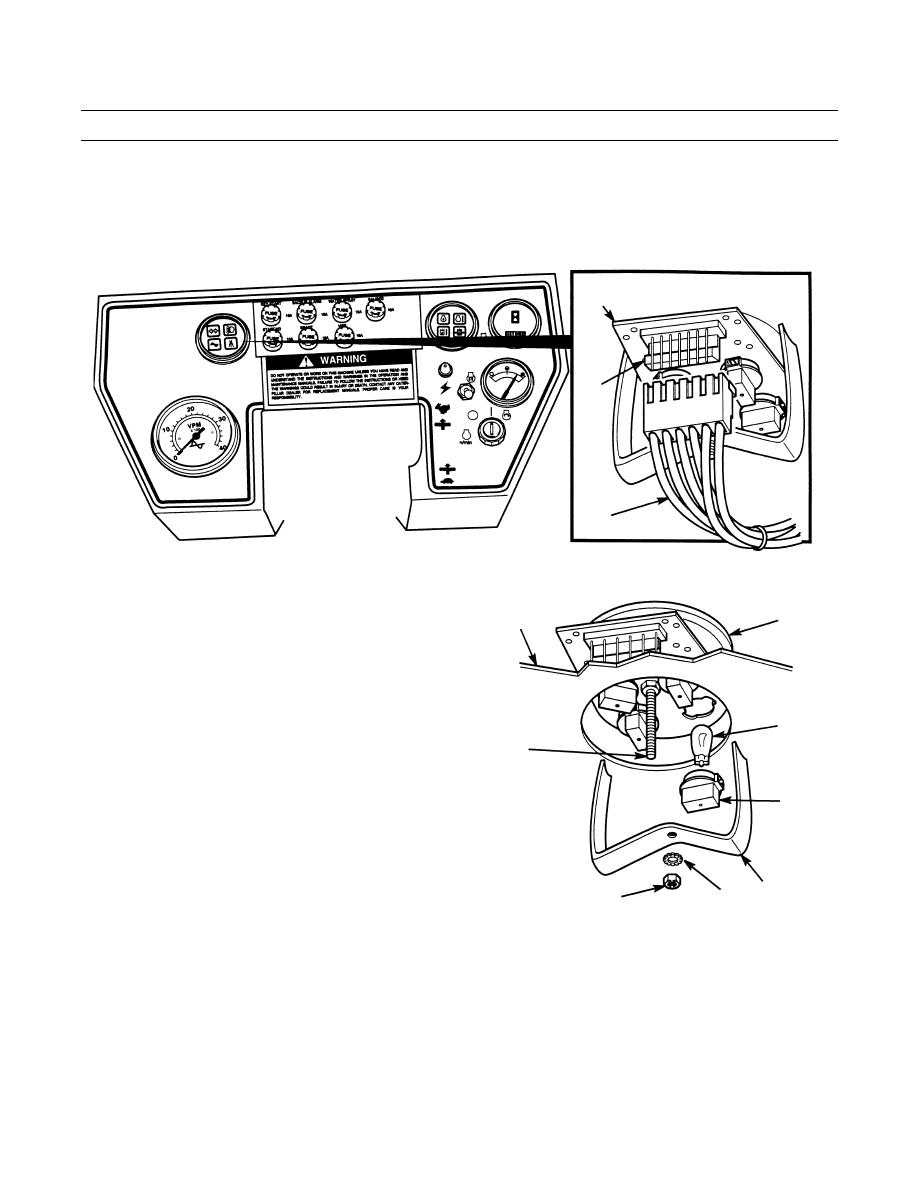
WARNING LIGHTS ASSEMBLY REPLACEMENT - CONTINUED
0093 00
REMOVAL - CONTINUED
NOTE
Tag and mark all wires prior to removal.
4.
Lift tab and disconnect connector (8) from warning lights assembly (9).
9
TAB
8
STEERING WHEEL SHOWN REMOVED FOR CLARITY
401-489
5.
Remove nut (10), lockwasher (11) and warning lights
9
4
assembly bracket (12) from stud (13). Discard lock-
washer.
6.
Remove warning lights assembly (9) from instrument
box assembly (4).
7.
Turn four lamp assemblies (14) counterclockwise and
15
remove from warning lights assembly (9).
13
8.
Remove four lamps (15) from lamp assemblies (14).
14
INSTALLATION
1.
Install four lamps (15) lamp assemblies (14).
2.
Install four lamp assemblies (14) in warning lights
assembly (9).
12
11
10
401-490
3.
Position warning lights assemblies (9) on instrument
box assembly (4).
NOTE
Before installing warning lights assembly bracket on warning lights assembly, ensure warning lights assem-
bly is positioned so icons are right-side up when instrument box assembly is installed.
4.
Install warning lights assembly bracket (12) on stud (13) with new lockwasher (11) and nut (10).
5.
Connect connector (8) to warning lights assembly (9).
0093 00-2
