
TM 5-3895-379-23-2
0231
ASSEMBLY
1.
If removed, install latch assembly (Figure 6, Item 2) and two guides (Figure 6, Item 3) on door assembly
(Figure 6, Item 1) with four bolts (Figure 6, Item 5) and washers (Figure 6, Item 4). Tighten bolts to
15-25 lb-ft (20-34 Nm).
2
1
3
4
5
3
M1178SWR
Figure 6. Door Assembly.
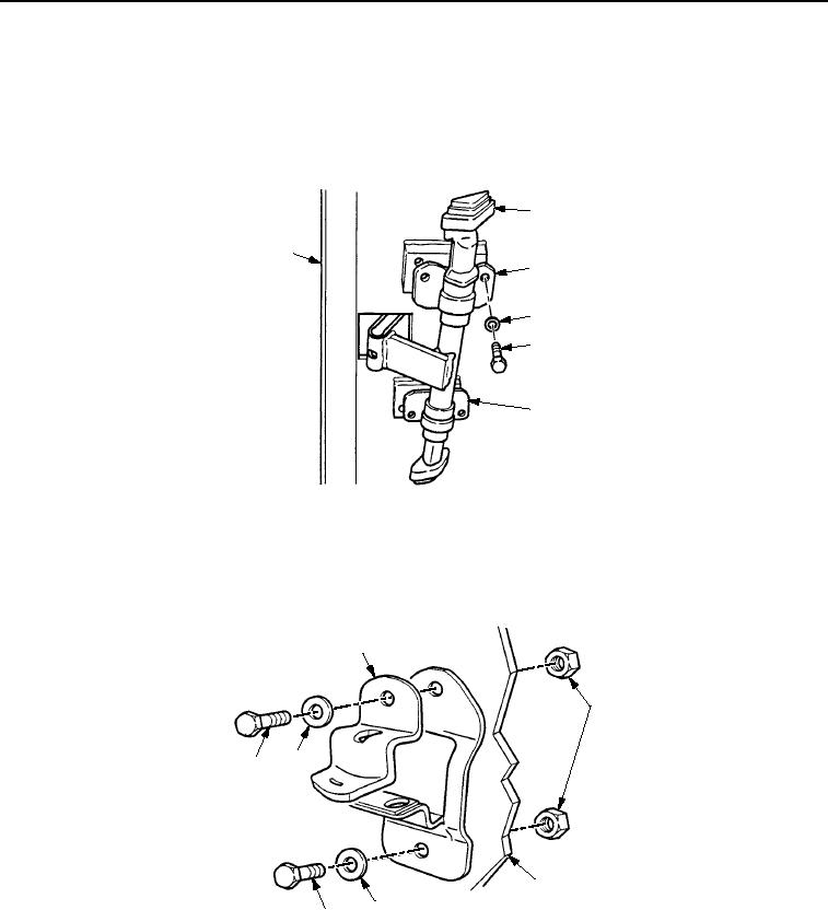
2.
If removed, install lock (Figure 7, Item 1) on door assembly (Figure 7, Item 3) with screw (Figure 7, Item 6),
bolt (Figure 7, Item 5), two washers (Figure 7, Item 4), and new locknuts (Figure 7, Item 2). Tighten locknuts
to 15-25 lb-ft (20-34 Nm).
1
2
4
6
3
4
5
M1177SWR
Figure 7. Door Assembly.
03/15/2011Rel(1.8)root(maintwp)wpno(M00169)