
TM 5-3895-379-23-1
0221
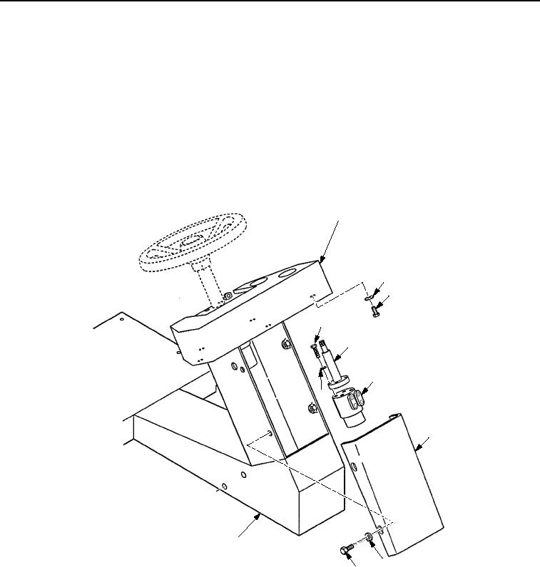
REMOVAL - Continued
4.
Remove four bolts (Figure 2, Item 9), washers (Figure 2, Item 8), and cover (Figure 2, Item 7) from station
(Figure 2, Item 10).
5.
Remove three bolts (Figure 2, Item 3) and washers (Figure 2, Item 2) that fasten console (Figure 2, Item 1) to
steering column (Figure 2, Item 5), and move console out of the way.
6.
While holding steering control unit (Figure 2, Item 6), remove four bolts (Figure 2, Item 4) and washers
(Figure 2, Item 11) that fasten steering control unit and steering column (Figure 2, Item 5) to console
(Figure 2, Item 1).
7.
Remove steering control unit (Figure 2, Item 6) from steering column (Figure 2, Item 5).
8.
Remove steering column (Figure 2, Item 5) from console (Figure 2, Item 1).
1
2
3
4
5
6
11
7
10
8
9
M0657SWR
Figure 2.
Steering Wheel and Column Removal.
END OF TASK
03/15/2011Rel(1.8)root(maintwp)wpno(M00159)