
TM 5-3895-379-23-1
0218
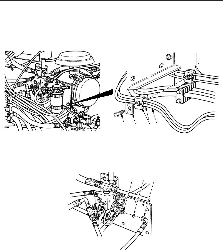
BRAKE VALVE TO REAR PROPEL GEARBOX LINE REPLACEMENT - Continued
15.
Remove screw (Figure 51, Item 5), plate (Figure 51, Item 4), clamp (Figure 51, Item 3), and hose
(Figure 51, Item 2) from screw (Figure 51, Item 1).
AIR CLEANER ASSEMBLY SHOWN
REMOVED FOR CLARITY
1
5
4
3
2
M0465SWR
Figure 51. Brake Hoses, Lines, and Replacement.
16.
Remove hose (Figure 52, Item 3) and O-ring (Figure 52, Item 2) from brake valve fitting (Figure 52, Item 1).
Discard O-ring.
17.
Install new O-ring (Figure 52, Item 2) and hose (Figure 52, Item 3) on brake valve fitting (Figure 52, Item 1).
1
2
3
M0466SWR
Figure 52. Brake Hoses, Lines, and Fittings Replacement.
18.
Place hose (Figure 51, Item 2) in clamp (Figure 51, Item 3) and install clamp and plate (Figure 51, Item 4) on
screw (Figure 51, Item 1), with screw (Figure 51, Item 5).
03/15/2011Rel(1.8)root(maintwp)wpno(M00156)