
TM 5-3895-379-23-1
0209
STABILIZED CONTROL VALVE SPOOL NEUTRAL ADJUSTMENT
NOTE
Prior to controlling the hydraulic servo, oil from the charge pump must control the spool of
the stabilized control valve.
1.
Perform the following test to verify valve spool neutral setting is correct.
NOTE
Hydraulic Servo Neutral Adjustment must be completed before performing this Stabilized
Control Valve Spool Neutral Adjustment. This is done to ensure that neutral
(mechanical center) position of servo piston and swash plate is correct.
2.
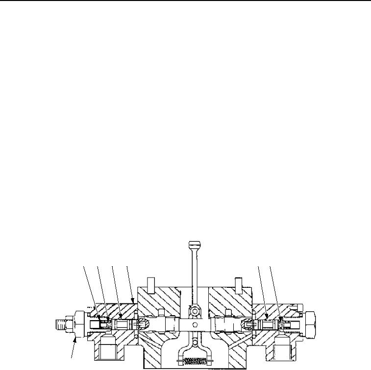
Remove two stabilized control valve end covers (Figure 13, Item 5).
NOTE
Leave springs and shim out for adjustment purposes.
3.
Remove two pistons (Figure 13, Item 3) with springs (Figure 13, Item 2) and shim (Figure 13, Item 1) from end
covers (Figure 13, Item 5).
4.
Install pistons (Figure 13, Item 3) back into stabilized control valve end covers (Figure 13, Item 5).
5.
Install two stabilized control valve end covers (Figure 13, Item 5) on the control valve body
(Figure 13, Item 4).
1
2
3
4
3
2
5
M0385SWR
Figure 13. Valve Tests and Adjustments.
03/15/2011Rel(1.8)root(maintwp)wpno(M00147)