
TM 5-3895-379-23-1
0125
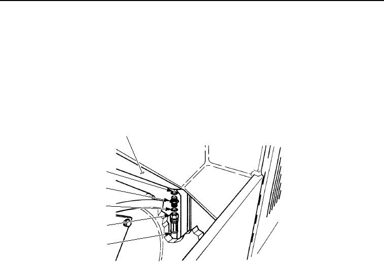
DRAIN LINES REMOVAL - Continued
NOTE
Hose assembly and fuel tank connection are located between rear roller drum and operator
platform.
3.
Loosen nut (Figure 2, Item 3) and remove hose assembly (Figure 2, Item 2) and O-ring (Figure 2, Item 4) from
fuel tank connector (Figure 2, Item 5). Discard O-ring.
4.
If damaged, remove fuel tank connector (Figure 2, Item 5) and O-ring (Figure 2, Item 6) from fuel tank
(Figure 2, Item 1). Discard O-ring.
1
6
5
4
3
2
M0513SWR
Figure 2. Drain Lines Removal.
03/15/2011Rel(1.8)root(maintwp)wpno(M00063)