
TM 5-3895-379-23-1
0091
INSTALLATION - Continued
NOTE
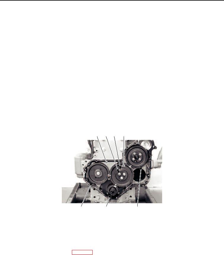
Drive gear of fuel injection pump may have to be turned clockwise to align timing marks
before installing idler gear.
Ensure timing marks on crankshaft gear, camshaft gear, and idler gear are aligned after
installation of idler gear.
4.
Install retaining plate (Figure 6, Item 3) and three bolts (Figure 6, Item 2) on idler gear (Figure 6, Item 4). Tighten
bolts to a torque of 33 lb-ft (45 Nm).
NOTE
Idler gear end play is between 0.004 to 0.008 in. (0.10 to 0.20 mm).
5.
Check idler gear (Figure 6, Item 4) end play. Replace idler gear if out of tolerance.
NOTE
Idler and camshaft gear end play must have a minimum backlash of 0.003 (0.08 mm).
6.
Check timing between camshaft gear (Figure 6, Item 7) and idler gear (Figure 6, Item 4). Replace idler gear if
out of tolerance.
1
2
3
4
M0090SWR
7
6
5
Figure 6. Idler Gear and Hub Installation.
END OF TASK
FOLLOW-ON MAINTENANCE
Install timing gear case cover. (WP 0092)
END OF TASK
END OF WORK PACKAGE
03/15/2011Rel(1.8)root(maintwp)wpno(M00030)