
TM 5-3895-379-23-1
0078
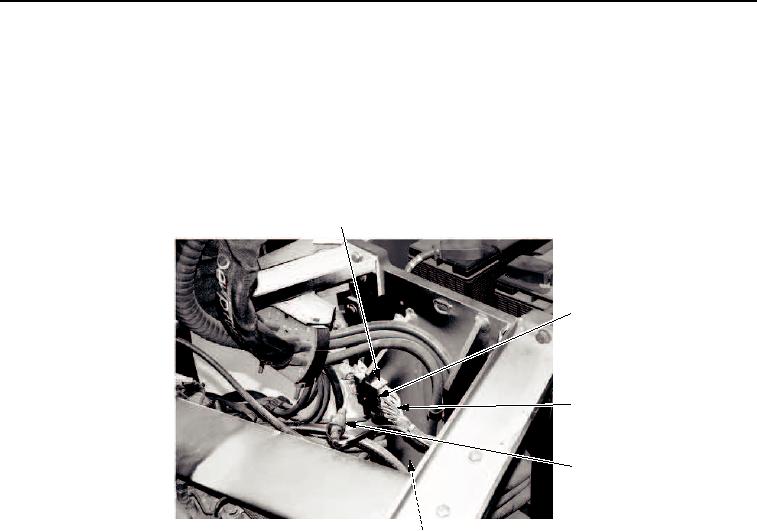
INSTALLATION - Continued
6.
Connect ground wire (Figure 27, Item 7) to frame with nut (Figure 27, Item 5) and washer (Figure 27, Item 6).
7.
Connect electrical connector (Figure 27, Item 1).
8.
Connect electrical connector (Figure 27, Item 4) by joining the connector halves.
9.
Install electrical connector (Figure 27, Item 4) with bolt (Figure 27, Item 3) and three screws
(Figure 27, Item 2).
1
2
3
4
5, 6, 7
M0031SWR
Figure 27. Engine Assembly Installation.
03/15/2011Rel(1.8)root(maintwp)wpno(M00017)