
TM 5-3895-379-23-1
0078
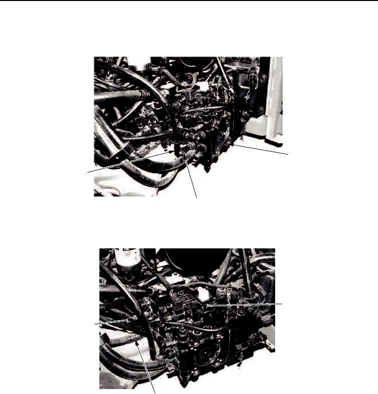
REMOVAL - Continued
7.
Disconnect hydraulic hoses (Figure 6, Items 2 and 3) from vibratory control valve (Figure 6, Item 1).
1
3
2
M0010SWR
Figure 6. Engine Assembly Removal.
8.
Disconnect hydraulic hoses (Figure 7, Items 2 and 3) from propel control valve (Figure 7, Item 1).
1
3
2
M0011SWR
Figure 7. Engine Assembly Removal.
03/15/2011Rel(1.8)root(maintwp)wpno(M00017)