
TM 5-3895-379-23-1
0067
TROUBLESHOOTING PROCEDURE
SYMPTOM
SPRAY DOES NOT OCCUR IN EITHER DRUM WHEN WATER SPRAY SWITCH IS IN CONTINUOUS SPRAY
POSITION
MALFUNCTION
No Power To Water Spray Switch.
CORRECTIVE ACTION
1.
Remove nine screws and washers and remove panel from operator station.
2.
Move water spray switch into continuous spray (full back) position.
3.
Turn battery disconnect switch to ON position (TM 5-3895-379-10).
4.
Turn engine start switch to ON position (TM 5-3895-379-10).
5.
Touch positive (+) probe of multimeter to terminal 2 (wire 110-GN).
6.
Touch negative (-) probe of multimeter to good ground.
If 24 to 28 VDC are not measured at terminal 2 (wire 110-GN) and WATER SPRAY fuse is
good, perform the following:
(1)
Turn engine start switch to OFF position (TM 5-3895-379-10).
(2)
Turn battery disconnect switch to OFF position (TM 5-3895-379-10).
(3)
Repair or replace wiring and connectors to water spray fuse holder (WP 0195).
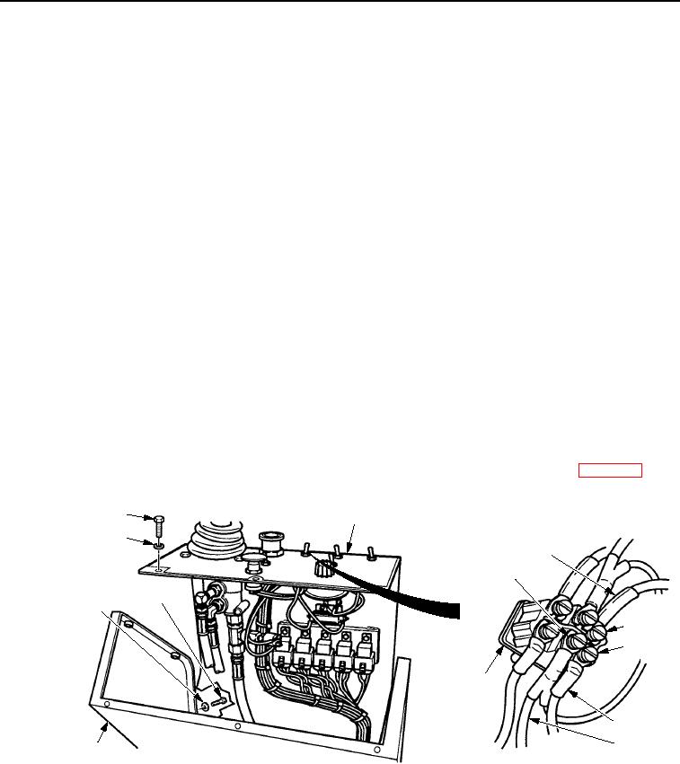
PANEL
SCREW
ASSEMBLY
WASHER
WIRE C923-OR
TERMINAL 2
SCREW
WASHER
TERMINAL 6
TERMINAL 3
WATER
SPRAY
SWITCH
WIRE C922-BR
WIRE 110-GN
OPERATOR
STATION
T0152SWR
Figure 1. Water Spray Switch Wiring.