
TM 5-3895-379-23-1
0058
MALFUNCTION
Amplitude Select Switch Faulty.
CORRECTIVE ACTION
1.
Set amplitude select switch to high pitch (push forward).
2.
Touch positive (+) probe of multimeter to terminal 1 (wire B921-WH).
3.
Touch negative (-) probe of multimeter to good ground.
4.
Measure VDC.
5.
Set amplitude select switch to low pitch (pull back).
6.
Touch positive (+) probe of multimeter to terminal 3 (wire B920-GN).
7.
Touch negative (-) probe of multimeter to good ground.
8.
Turn engine start switch to OFF position (TM 5-3895-379-10).
9.
Turn battery disconnect switch to OFF position (TM 5-3895-379-10).
a.
If 24 to 28 VDC are not measured at both terminals 1 and 3, replace amplitude select
switch (WP 0160).
b.
If 24 to 28 VDC are measured at terminals 1 and 3, repair or replace wiring and connectors
from amplitude select switch (WP 0195).
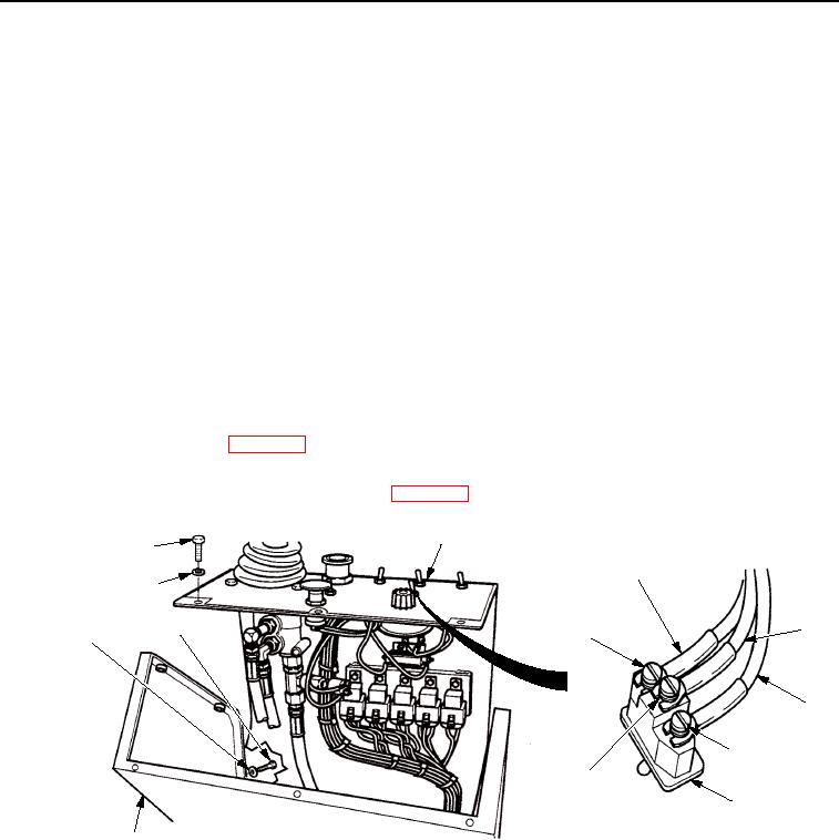
PANEL ASSEMBLY
SCREW
WIRE C920-GN
WASHER
SCREW
WIRE
TERMINAL 3
WASHER
C933-GN
WIRE
B921-WH
TERMINAL 1
TERMINAL 2
AMPLITUDE
SELECT SWITCH
T0234SWR
OPERATOR STATION
Figure 8. Amplitude Select Switch Wiring.
END OF WORK PACKAGE
0058-11/12 blank
03/15/2011Rel(1.8)root(tswp)wpno(T00064)