
TM 5-3895-379-23-1
0058
MALFUNCTION
No Power To Vibration Push Switch.
CORRECTIVE ACTION
1.
Turn engine start switch to ON position (TM 5-3895-379-10).
2.
Touch positive (+) probe of multimeter to wire 103-YL.
3.
Touch negative (-) probe of multimeter to good ground.
4.
Turn engine start switch to OFF position (TM 5-3895-379-10).
5.
Turn battery disconnect switch to OFF position (TM 5-3895-379-10).
a.
If 24 to 28 VDC are not measured at wire 103-YL and VIBE fuse is good, perform the
following:
(1)
Repair or replace wiring and connectors to VIBE fuse holder (WP 0195).
(2)
Install vibration push switch (WP 0167).
b.
If 24 to 28 VDC are measured at wire 103-YL, install vibration push switch (WP 0167) and
go to next malfunction.
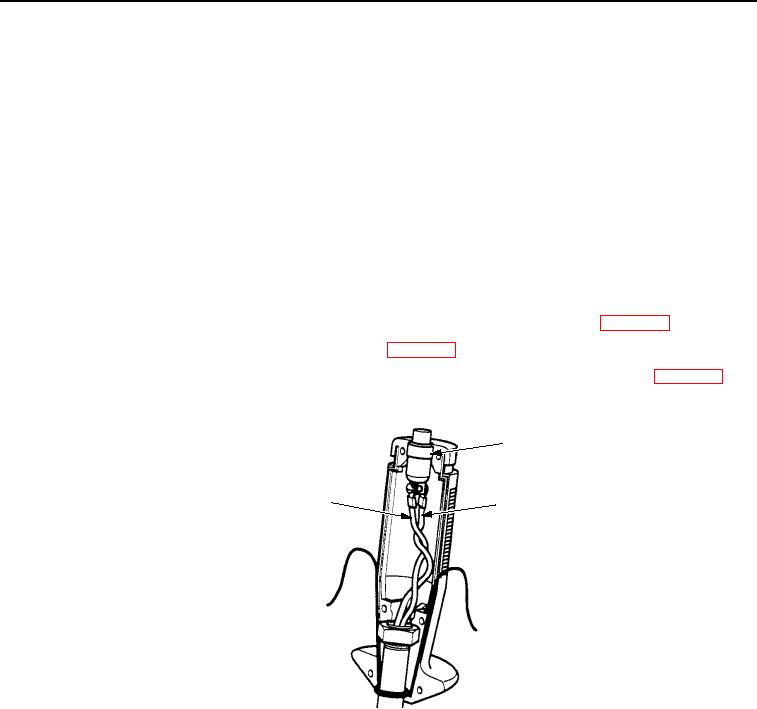
VIBRATION
PUSH SWITCH
WIRE 103-YL
WIRE 932-YL
T0136SWR
Figure 3. Vibration Push Switch Wiring.