
pressure relief valves located in the motor manifold.
TROUBLE SHOOTING PROCEDURE
The relief valves have a two (2) digit number stamped
Before Proceeding With Trouble Shooting, Read the
on the exposed end stating valve setting (i.e. "50" =
Following Information!
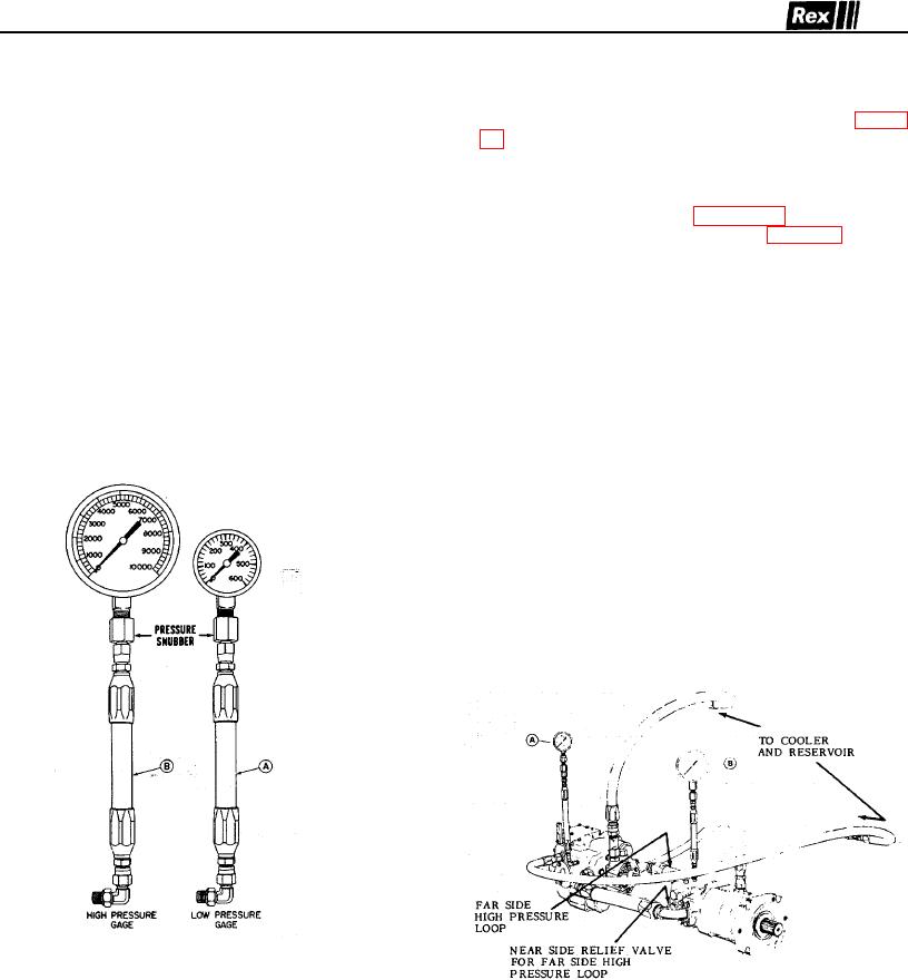
5000 psi). High pressure gauge port (Gauge "B", figure
Sundstrand Heavy Duty transmissions must maintain
11) monitors far side high pressure' loop' and near side
various pressures to function properly. Any disturbance
relief valve.
of the proper pressure levels will lead to an inoperable
transmission.
The necessary gauges and complimentary equipment
required are depicted in Figure 10. Their proper
1. CHARGE PRESSURE: The minimum allowable
installation in the circuit is depicted in Figure 11.
charge pressure is 130 p.s.i. Normal charge pressure is
160 p.s.i. and 190 p.s.i. when pump is in neutral.
NOTE: For accurate gauge interpretation, it is
recommended that the pump drive shaft be turning at or
near
2. SYSTEM OR HIGH PRESSURE: The maximum
maximum RPM.
system pressure obtainable is controlled by the high
A. Gauge Connection = 7/16 x 20 SAE "O" Ring -
All Series
B. Gauge Connection = 7/16 x 20 SAE "O" Ring -
All Series
TROUBLE SHOOTING GAUGES
FIGURE 10
TYPICAL GAUGE INSTALLATION (PV-MF)
FIGURE 11
44