
Engine Tune-Up
DETROIT DIESEL
THROTTLE DELAY MECHANISM
The throttle delay mechanism is used to retard full- fuel injection when the engine is accelerated. This reduces exhaust
smoke and also helps to improve fuel economy.
The throttle delay mechanism (Fig. 2) is installed between the No. 1 and No. 2 cylinders on three cylinder engines,
between the No. 2 and No. 3 cylinders on four cylinder engines, or between the No. I and No. 2 cylinders on the right-
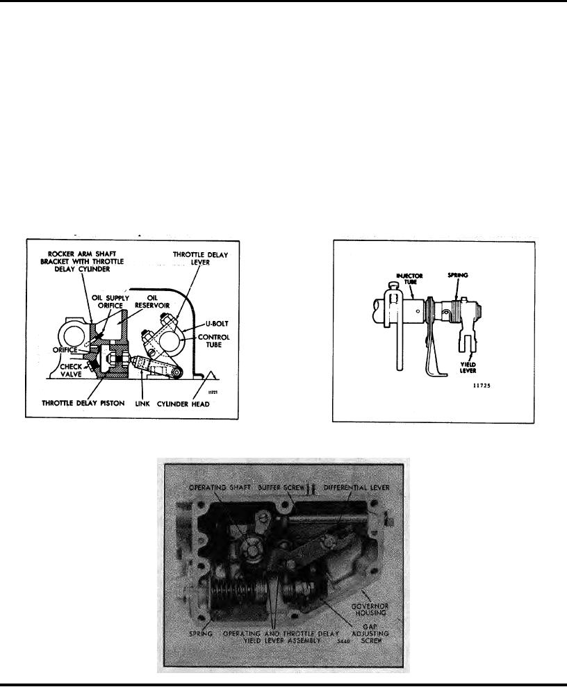
bank cylinder head of V-type engines. It consists of a special rocker arm shaft bracket (which incorporates the throttle
delay cylinder), a piston, throttle delay lever, connecting link, oil supply plug, ball check valve and U-bolt.
A yield lever and spring assembly replaces the standard lever and pin assembly on the rear end of the injector control
tube on In-line engines (Fig. 3). A yield lever replaces the standard operating lever in the governor of the 6V-53 engine
(Fig. 4).
Operation
Oil is supplied to a reservoir above the throttle delay cylinder through a special plug in the drilled oil passage in the
rocker arm shaft bracket (Fig. 2). As the injector racks are moved toward the no-fuel position, free movement of the
throttle delay piston is assured by air drawn into the cylinder through the ball check valve. Further movement of the
piston uncovers an opening which permits oil from the reservoir to enter the cylinder and displace the air. When the
engine is accelerated, movement of the injector racks toward the full-fuel position is momentarily retarded while the
piston expels the oil from the cylinder through a .016"orifice. To permit full accelerator travel, regardless of the retarded
injector rack position, a spring loaded yield lever or link assembly replaces the standard operating lever connecting link to
the governor.
Fig. 2 - Throttle Delay Cylinder
Fig. 3 - Throttle Delay Yield Lever (In-Line
Engine)
Fig. 4 - Throttle Delay Yield Lever (6V Engine)
Page 104