DETROIT DIESEL
Engine Tune-Up
HYDRAULIC GOVERNOR AND INJECTOR RACK CONTROL ADJUSTMENT
6V-53 ENGINE
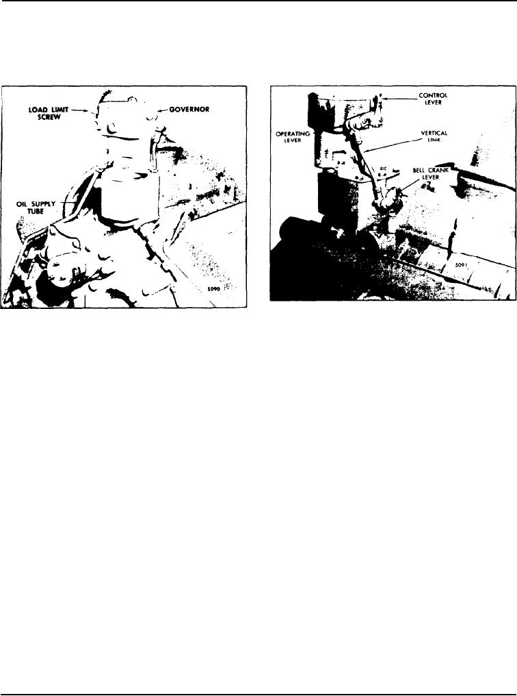
Fig. 2 Hydraulic Governor Controls
Fig. 1 - Hydraulic Governor Mounting
lever, adjust the load limit screw to obtain a distance
The hydraulic governor is mounted between the
of 2" from the outside face of the boss on the
blower and the rear end plate as shown in Fig. 1. The
governor sub-cap to the end of the screw.
vertical control link assembly is attached to the
governor operating lever and the bell crank lever on
7. Adjust the operating lever (on the governor) so that
the governor drive housing (Fig. 2).
it is horizontal, or slightly below (as close as the
serrations on the shaft will permit) when the shaft is
After adjusting the exhaust valves and timing the fuel
rotated to the full-fuel position, or clockwise when
injectors, adjust the governor as follows:
viewed from the front of the engine.
8. Loosen the lock nut and adjust the length of the
1. Disconnect the vertical control link assembly from
vertical link assembly, attached to the bell crank lever,
the governor operating lever.
to match the full-fuel position of the governor
operating lever and the injector rack control levers.
2. Loosen all of the injector rack control lever
T h i s length should be approximately 6-5/16"
adjusting screws.
Tighten the lock nut.
3. While holding the bell crank lever (on the governor
9. With the governor operating lever held in the full-
drive housing) in a horizontal position (full-fuel), set
fuel position, turn the load limit screw ((Fig. 1) inward
the No. 3 injector rack control levers on each bank to
until the injector racks just loosen on the ball end of
full-fuel.
the control levers, to prevent the injector racks from
bottoming.
4. Position the remaining rack control levers to the
No. 3 control levers.
10. Release the governor operating lever and hold the
adjusting screw while tightening the lock nut.
5. Remove the governor cover. Discard the gasket.
11. Use new gaskets and install the governor cover and
6. To determine the full-fuel position of the terminal
the valve rocker covers.
Page 111

