
136. Valves and Tappets
a. General. The intake and exhaust valves are accessible by removing the valve cover (11, fig. 50) and gasket (3).
The ventilation pipe is welded to the valve cover (11) and cannot be removed. Both valves operate in the valve guides
pressed into the engine block. The valves can be adjusted without removing the cylinder head. It is advisable to remove
the manifold assembly to facilitate the valve adjustment.
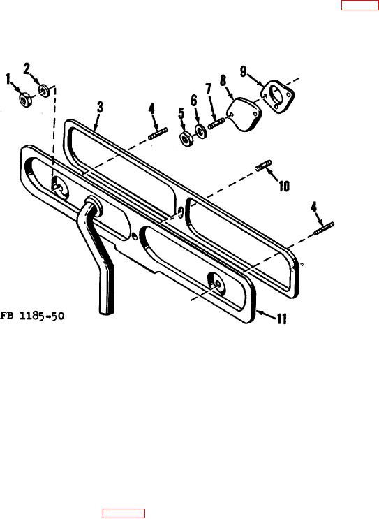
1
Cover nuts, 1/4-28NF (3 req'd)
6 Washers, lock, std, 5/16 (2 req'd)
2
Stud gasket
7 Cover studs, 5/16-24NF x 1 1/4 (2
3
Valve chamber cover gasket
req'd)
4
Cover end studs, 1/4-28NF x 1 (2
8 Fuel pump hole cover
req'd)
9 Cover gasket
5 Fuel pump cover nuts, 5/16-24NF (2
10 Cover center stud, 1/4-28NF x 3 1/4
req'd)
11 Valve chamber cover
Figure 50. Valve chamber cover and fuel pump cover disassembled.
b. Adjustment.
(1) Run the engine until normal operating temperature is reached. Shut off the engine.
(2) Remove the manifold assembly (par 132b).
(3) Remove the valve cover stud nuts (1) and gaskets (2).
(4) Remove the valve cover (11) and valve cover gasket (3). Discard the gasket (3).
(5) Use three open-end tappet wrenches and a 0.014 feeler gage for-the adjustment of the valve-tappet
clearance. Use 0.015 feeler gage if the engine is cool.
137