
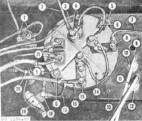
1
Starter button terminal nut
12
Throttle cable mounting nut
2
Starter button lead
13
Instrument panel bracket
3
Oil gage lead
14
Cluster gage
4
Oil gage terminal nut
15
Temperature gage terminal nut
5
Cluster gage clamp
16
Temperature gage lead
6
Clamp nut
17
Shielding strap
7
Fuel gage lead
18
Capacitor nut
8
Fuel gage terminal nut
19
Capacitor
9
Choke cable
20
Ignition switch
10
Choke cable mounting nut
21
Ammeter terminal nut
11
Throttle cable
Figure 37. Instrument panel, rear view.
(6) Remove the mounting nuts (6) and clamps (5) and remove the cluster gage (14) from the front side of the
instrument panel bracket (13).
c. Cluster Gage Inspection. Inspect the oil pressure, fuel, temperature, and ammeter gages for proper operation. If
one of the gages is damaged or defective, the entire cluster gage assembly must be replaced. The cluster gage assembly
is not repairable.
d. Cluster Gage Installation.
(1) Position the cluster gage (14) over the mounting hole in the instrument panel bracket (13) so that the oil
pressure gage is on the top, and the temperature gage is on the bottom of the instrument panel.
108