
TM 5-3895-379-23-2
0222
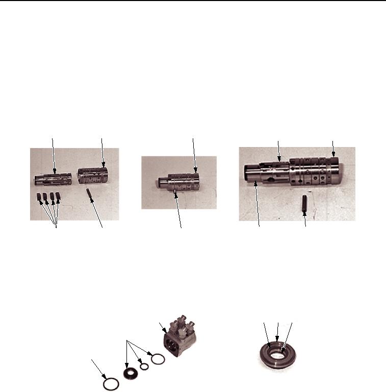
DISASSEMBLY - Continued
10.
Remove pin (Figure 6, Item 6) from spool (Figure 6, Item 2) and sleeve (Figure 6, Item 3) (slip fit).
11.
Separate control spool (Figure 6, Item 2) and sleeve (Figure 6, Item 3).
NOTE
Spring kit has four centering springs.
Components of the gerotor assembly shown in photo.
12.
Remove centering spring kit (Figure 6, Item 7) from control spool (Figure 6, Item 2).
1
2
2, 3
2
3
4
7
5
4
6
M0668SWR
Figure 6. Steering Control Unit (SCU) Disassembly.
13.
Remove retaining ring (Figure 7, Item 1) and gland bushing (Figure 7, Item 2) from the control housing
(Figure 7, Item 3). Discard retaining ring.
14.
Remove dust seal (Figure 5, Item 4) from gland seal (Figure 5, Item 5). Turn seal gland bushing over and
remove quad ring seal (Figure 5, Item 6). Discard dust seal and quad ring seal.
3
4
5
6
2
1
M0671SWR
Figure 7. Steering Control Unit (SCU) Disassembly.
03/15/2011Rel(1.8)root(maintwp)wpno(M00160)

