
TM 5-3895-379-23-2
0222
DISASSEMBLY - Continued
15.
Remove set screw (Figure 8, Item 2) from control housing (Figure 8, Item 3).
16.
Install 1/8 in. - 24 machine screw into the end of the check ball seat (Figure 8, Item 4). Remove the check ball
(Figure 8, Item 4) seat with pliers.
1
2
3
4
M0672SWR
Figure 8. Steering Control Unit (SCU) Disassembly.
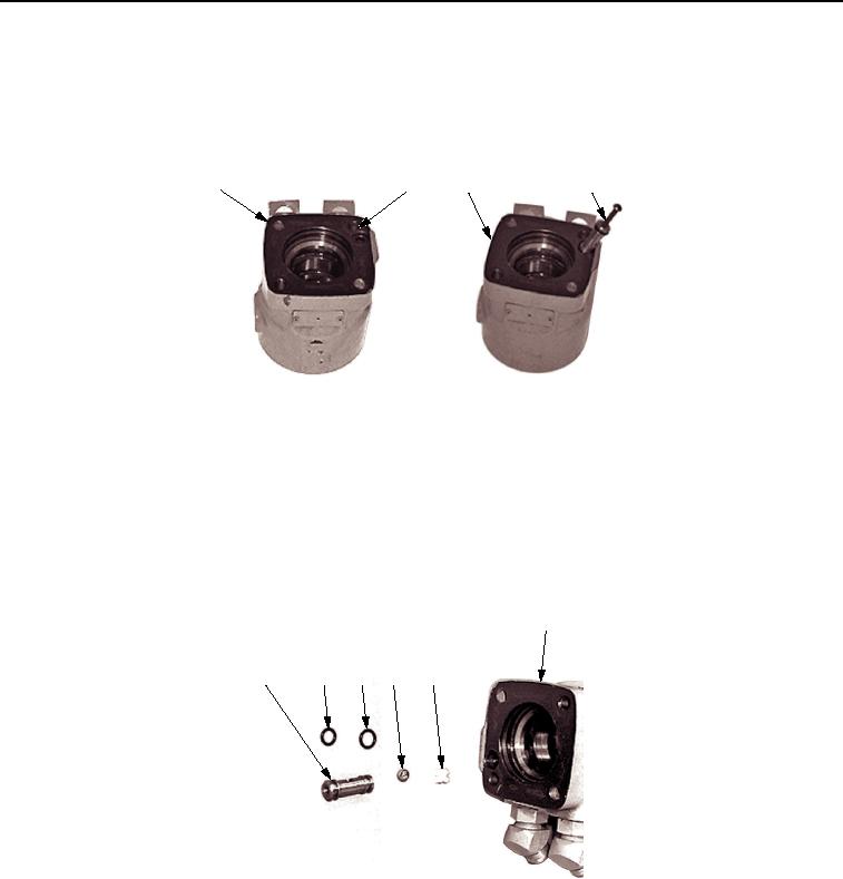
NOTE
O-rings are different sizes. Note their location on the check ball seat prior to removal. Do not
mix when re-installed.
17.
Remove check ball (Figure 9, Item 4) and check ball retainer (Figure 9, Item 5) from the control housing
(Figure 9, Item 6).
18.
Remove O-rings (Figure 9, Items 2 and 3) from check ball seat (Figure 9, Item 1). Discard O-rings.
6
1
2
3
4
5
M0674SWR
Figure 9. Steering Control Unit (SCU) Disassembly.
END OF TASK
03/15/2011Rel(1.8)root(maintwp)wpno(M00160)

