TM 5-3895-383-24
The axle is used to transmit power from the propel motor to the
rear wheels. Power from the axle propel motor goes through
wheel drive gearbox (4) to the TrueTrac differential (2). The
power from the TrueTrac differential goes through the left and
right planetary gears to the axle shafts. The axle shafts have
flanges (5) in order to mount the wheels. The wheels transfer
the power to the ground.
Illustration 60
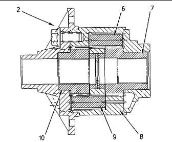
TrueTrac Differential
(2) TrueTrac differential. (6) Pinion. (7) Side gear. (8) Case.
(9) Pinion. (10) Side gear.
The TrueTrac differential is a gear type limited slip differential.
The following features are the two main functions of the
TrueTrac differential.
1.
The TrueTrac differential limits the wheel spin and the
power loss when one wheel loses traction.
2.
The TrueTrac differential allows differences in wheel
speed when the machine is in a turn or on an uneven
surface.
When the machine is operated in a straight direction and over
a smooth surface, the TrueTrac differential operates as a
standard differential. Equal force is applied to each side gear
(7) and (10). Essentially, the TrueTrac differential equally
divides the power between the rear wheels.
The TrueTrac differential automatically engages when the
compactor makes a turn, or when one of the wheels loses
traction. One of the pinions (6) or (9) separates from the side
gear (7) or (10). This causes the pinion to wedge into the
pockets in the case (8). In this case, the TrueTrac differential
proportionally distributes the torque to each wheel so that the
wheel with the poorest traction will be controlled. The majority
of the torque is transferred to the wheel with the most solid
footing.
NOTE:
The TrueTrac differential will not engage when
one of the wheels is off the ground. A small
amount of resistance must be applied to this
wheel in order for the TrueTrac differential to
property engage.
Illustration 61
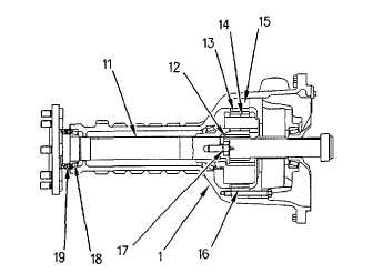
Left Axle Housing Assembly
(1) Left axle housing assembly. (11) Axle shaft. (12) Sun
gear. (13) Planetary gears. (14) Needle bearings. (15) Ring
gear housing. (16) Planetary ring gear. (17) Axle shaft
retaining bolt. (18) Axle bearing. (19) Seal.
The planetary ring gears (16) are pressed into ring gear
housings (15). The planetary gears are positioned around the
sun gear (12) and within the planetary ring gear (16).
Planetary gears (13) are mounted to the carrier by shafts and
the planetary gears rotate on needle bearings (14). Each
carrier is located inside the planetary ring gears (16). The
carriers will rotate at a slower speed than the sun gears. The
carriers are connected to axle shaft (11) with internal splines.
Axle shaft (11) is mounted in a tapered roller bearing and the
end play is adjusted via a shim under axle shaft retaining bolt
(17).
10-53


