TM 5-3895-383-24
6.
While holding rack head (5) in the shutoff position,
adjust dial indicator (2) until all three dials read zero.
Then tighten the dial indicator. Release rack head (5).
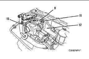
Governor
(9) Clip. (10) Governor. (11) Sleeve. (12) Inlet manifold.
7.
Remove clip (9) that keeps sleeve (11) in position
between governor (10) and inlet manifold (12).
NOTE:
Do not use hard-jawed pliers or screwdriver to
move sleeve (11). Damage may result to sleeve
(11) which will damage the wiper seal in the inlet
manifold when sleeve (11) is installed in inlet
manifold.
8.
With 6V0006 Pliers, slide sleeve (11) from governor (10)
toward inlet manifold (12).
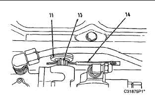
Install Governor Pin
(11) Sleeve. (13) Link pin. (14) 1U7305 Insertion Tool.
9.
Install 1U7305 Insertion Tool (14) into link pin (13) of the
governor output shaft. When properly installed, equal
lengths of the small diameter of tool (14) will extend
from both ends of link pin (13).
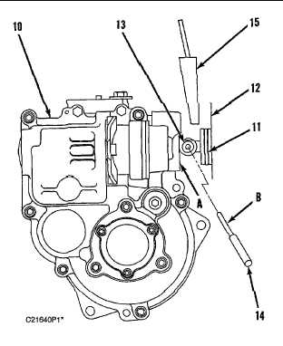
Governor Viewed From Rear
(10) Governor. (11) Sleeve. (12) Inlet manifold. (13) Link pin.
(14) 1U7305 Insertion Tool. (15) 1U6681 Holding Tool. (A)
Face of governor. (B) Small diameter of tool.
10.
Install 1U6681 Holding Tool (15) between sleeve (11)
and small diameter (B) of 1U7305 Insertion Tool (14).
Push holding tool (15) down until small diameter (B) of
tool (14) contacts face (A) of governor (10). This is the
fuel setting measurement position.
NOTE:
If the small diameter (B) of 1U7305 Insertion Tool
(14) does not contact face (A) of governor (10),
remove the air line at the FRC. Use FT1906
Fabricated Tester and apply 105 kPa (15 psi) air
pressure to the FRC. Pressurizing the FRC will
prevent the FRC from interfering with the rack
control linkage, and will allow the small diameter
(B) of 1U7305 Insertion Tool (14) to contact face
(A) of governor (10). After the fuel setting check
is completed, remove FT1906 and install the air
line on the FRC.
6-68


