
TM 5-3895-379-23-2
0244
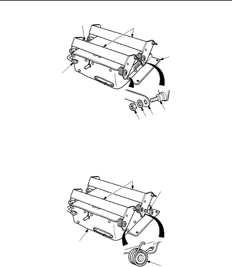
DISASSEMBLY - Continued
1
2
3
6
2
1
4
5
M0782SWR
Figure 3. Seat Suspension Disassembly.
9.
Pry ends of two torsion springs (Figure 4, Item 3) on right-side of seat suspension assembly (Figure 4, Item 4)
from two links (Figure 4, Item 1).
10.
Using a socket wrench screwdriver attachment, remove four bolts (Figure 4, Item 2), two links
(Figure 4, Item 1), and two torsion springs (Figure 4, Item 3).
1
2
4
3
M0783SWR
Figure 4. Seat Suspension Disassembly.
03/15/2011Rel(1.8)root(maintwp)wpno(M00182)