
TM 5-3895-379-10
DESCRIPTION AND USE OF OPERATOR'S CONTROLS AND INDICATORS - CONTINUED
0004 00
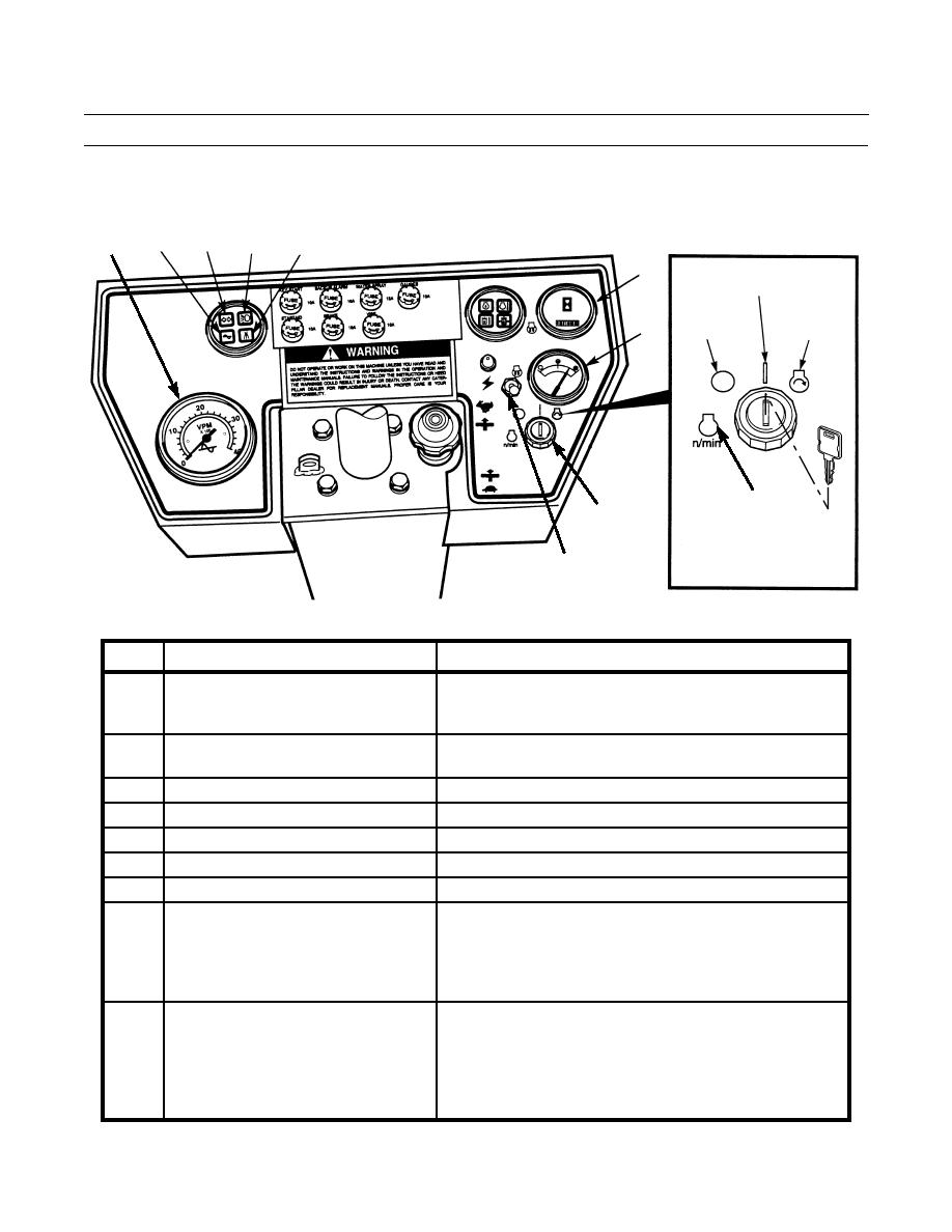
CONTROLS AND INDICATORS
2
4
3
5
1
6
ON
POSITION
START
OFF
POSITION
POSITION
7
THIS SYMBOL DOES
9
NOT APPLY TO
ENGINE START
SWITCH ON
8
MILITARY MODEL
STEERING WHEEL NOT SHOWN
FOR CLARITY
401-2162
KEY
CONTROL OR INDICATOR
FUNCTION
1
Vibration Per Minute (VPM) Tachometer Indicates vibrations per minute (frequency of drum vibration).
Gauge reading indicates the VPM of weight shafts of drum(s)
selected by the position of the vibratory mode control switch.
2
Vibratory System Indicator
When illuminated, indicates the vibration push switch is in the
ON position.
3
Turn Signal Indicator
Not used.
4
Lights Indicator
When illuminated, indicates the lights are on.
5
Water Spray System Indicator
When illuminated, indicates the water spray system is activated.
6
Service Hourmeter
Displays the total number of hours the engine has been operated.
7
Fuel Level Gauge
Indicates the amount of diesel fuel or JP-8 in the fuel tank.
8
Starting Aid Switch
On the CB534B, the starting aid switch powers the cold start
heater which warms a small amount of fuel that enters the
combustion chamber. The heater is used in cold weather to help
start the engine. On the CB534C, the switch powers the air inlet
heater which warms the air that enters the engine.
9
Engine Start Switch
Ignition key controls the mode of engine and electrical system.
The START (full right) position is used to crank the engine for
starting. The ON (right) position is used to activate all electrical
circuits and allows the engine to run once it is started. The OFF
(left) position stops the engine and shuts down all electrical
circuits.
0004 00-2
