DETROIT DIESEL 53
Shop Notes 2.0
3. The bluing solution bath.
4. A cold water rinse.
5. An engine lubricating oil bath (180 -212 F.) to rust proof. The bluing tank should be a double walled, 1-1/
2 " insulated type of No. 10 gage steel.
The temperature of the sodium hydroxide, sodium nitrite and phosphoric acid solution for bluing steel parts
should be 295 to 305 F. The boiling point of the solution is directly related to its concentration. Therefore,
when the boiling point is too high, the solution is too concentrated and the volume of water is probably low.
When this occurs, the boiling point can be reduced to 300 F. by adding water. The parts should be placed in
the solution for 15 to 30 minutes.
It is extremely important that the parts be free of oil before placing them in the bluing bath. Oil will produce a
varied color part.
There are several important safety precautions to be followed for preparing and using the solutions. Protective
clothing such as rubber gloves, rubber aprons and protective glasses contribute to the safety of personnel
carrying out the procedures. When preparing the solutions, the compounds should be added to the water and
not water added to the compounds. The dipping tanks should be properly vented and all fumes exhausted to
the outside atmosphere. Since temperatures of the caustic solutions exceed the boiling point of water, any
splashing encountered while adding make-up water can cause serious burns. Always add water slowly and with
extreme care. When the parts to be dipped are cold, caution should be taken to avoid splashing that might
occur when the cold parts come in contact with the hot solutions. A heavy wire-screen type basket, suitable for
holding a quantity of injector bodies, is recommended for dipping the parts in the solutions.
INJECTOR COMPARATOR AND CALIBRATION READINGS
Several factors affect the injector comparator and
calibrator output readings. The four major items are:
1.
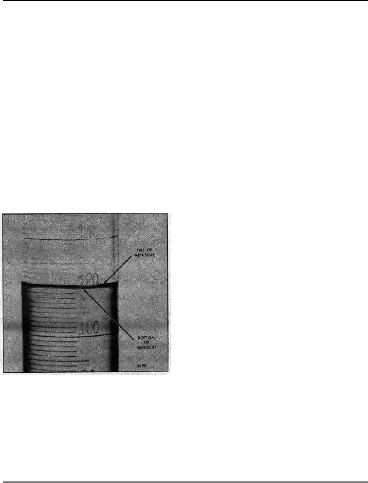
Operator Errors: If the column of liquid in the
vial is read at the top of the meniscus instead of at the
bottom, a variation of I or 2 points will result. Refer to
Fig. 3.
Air In Lines : This can be caused by starting a
2.
test before the air is purged from the injector and lines, or
from an air leak on the vacuum side of the pump.
3.
Counter Improperly Set: The counter is set at the
factory to divert the injector output at 1,000 strokes,
This should not be confused with counter overrun that will
vary from 2 to 6 digits, depending upon internal friction.
The fuel diversion is accomplished electrically and will
occur at 1,000 strokes (if properly set) although the
counter may overrun several digits.
4.
Test Oil: A special test oil is supplied with the
Fig. 3 - Checking Fuel Output
calibrator and the comparator and should always be used.
If regular diesel fuel oil (or any other liquid) is used, variations are usually noted because of the affect of the oil
on the solenoid valve and other parts.
The fuel oil introduced into the test oil when the fuel injector is placed in the comparator or calibrator for a
calibration check contaminates the test oil. Therefore, it is important that the comparator or calibrator have the
test oil and test oil filter changed every six months, or sooner if necessary.
In addition, other malfunctions such as a slipping drive belt, low level of fuel oil, a clogged filter, a defective
fuel pump or leaking line connections could cause bad readings. A frequent check should be made
for any of these tell-tale conditions.
August, 1972 SEC. 2.0
Page 3

