
1.7.7 Accessory Drive
DETROIT DIESEL 53
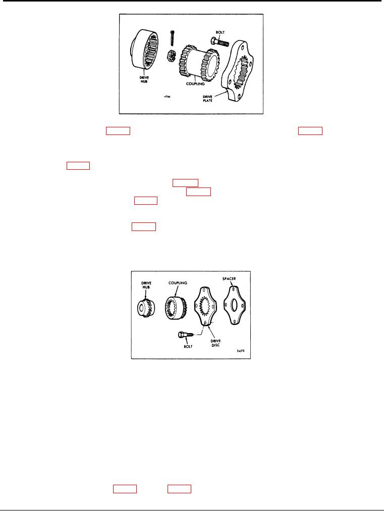
Figure 3. Air Compressor Drive
The drive plate and spacer, when used, are bolted to the camshaft or balance shaft gear. The accessory is
bolted to the flywheel housing and driven by a drive hub keyed to the accessory shaft and splined to the
coupling which is splined to the drive plate attached to the camshaft or balance shaft gear. The current drive
coupling, shown in Fig. 4, has 21 external teeth; the former coupling had 23 external teeth.
Belt driven accessories, such as battery-charging generators or air compressors, are driven off the camshaft or
balance shaft gears by a drive hub and pulley (Fig. 5), or a spacer, accessory drive plate, accessory drive
shaft, accessory drive retainer assembly and pulley (Fig. 6).
In the first arrangement, illustrated in Fig. 5, the drive hub is bolted to the camshaft or balance shaft gear. The
oil seal retainer is bolted to the flywheel housing and the pulley is keyed to the drive hub shaft which extends
through the oil seal retainer.
In the second arrangement, shown in Fig. 6, the spacer and accessory drive plate are bolted to the camshaft or
balance shaft gear. The accessory drive shaft is splined to the drive plate at one end and supported by a
bearing in the accessory drive retainer at the other end. The accessory drive retainer, which also incorporates
an oil seal, is bolted to the flywheel housing. The pulley is keyed to the drive shaft which extends through the
drive retainer assembly.
Figure 4. Hydraulic Pump Drive
Remove Accessory Drive
Remove the direct gear driven type accessory drive as follows:
1. Remove any external piping or connections to the accessory.
2. Remove the five bolts and lock washers attaching the accessory to the flywheel housing. Pull the
accessory straight out from the flywheel housing.
3. Remove the drive coupling.
4. Remove the drive hub from the accessory shaft. If necessary.
5. Place a clean, lintless cloth in the flywheel housing opening, underneath the accessory drive plate, to
prevent bolts from accidentally falling into the gear train. Remove the lock wires, if used. Then remove the
four bolts (and lock washers, if used) and remove the accessory, the drive plate and the spacer, if used.
Remove the drive assembly for a belt driven type accessory as follows:
I. Remove any external piping or connections to the accessory.
2. Loosen the accessory and slide it toward the drive pulley. Then remove the drive belt and accessory.
4. Use a suitable gear puller to remove the pulley from the drive shaft. Remove the Woodruff key.
5. Remove the five bolts and lock washers which attach
Page 2