
DETROIT DIESEL 53
1.7.4
IDLER GEAR AND BEARING ASSEMBLY
IN-LINE
ENGINES
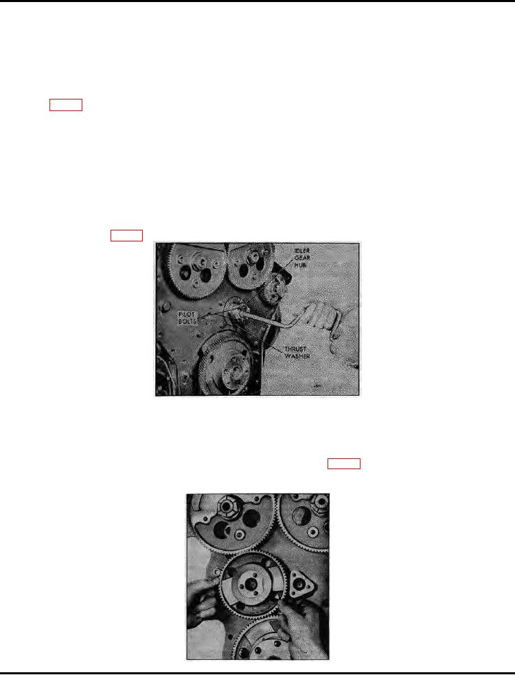
The engine idler gear and bearing assembly, located at the flywheel end of the engine, meshes with the
camshaft and crankshaft gears and rotates on a stationary hub. The hub is secured directly to the cylinder
block by a bolt which passes through the hub and three bolts which pass through the flywheel housing, hub and
end plate (Fig. 1).
Two timing marks (a triangle within a circle) are stamped on the idler gear diametrically opposite (180) to one
another.
The inside diameter of the idler gear bearing is 2.186 "-2.187 " and the outside diameter of the idler gear hub is
2.1825 "-2.1835 ". Therefore, the clearance between the idler gear hub and the idler gear bearing is .0025 " to
.0045 ", with a maximum allowable wear limit of .007 ".
A thrust washer is provided on both sides of the idler gear and bearing assembly. The standard thickness of
the idler gear and bearing assembly is 1.233 " to 1.234 " and the standard thickness of the two thrust washers is
.236 " to .240 "; thus, the clearance between the thrust washers and the idler gear is .006 " to .013 ", with a
maximum allowable wear limit of .017 "
On an In-line engine, the idler gear is positioned on the left-hand side for a right-hand rotating engine as viewed
from the rear. Refer to Fig. 5 under General Description.
Figure 1. Installing Idler Gear Hub
On early engines, an idler gear spacer (dummy hub) was used on the side opposite the idler gear. Currently
the flywheel housing has an integral cast hub and a .015 " thick shim is used between the flywheel housing and
the end plate.
Remove Idler Gear and Bearing Assembly (Flywheel Housing Removed)
1. Remove the idler gear outer thrust washer from the idler gear hub (Fig. 3).
2. Slide the idler gear straight back off of the idler gear hub.
3. Remove the bolt which secures the idler gear hub to
Figure 2. Installing Idler Gear
August, 1972 SEC. 1.7.4 Page 1