
DETROIT DIESEL 53
4.1
LUBRICATING OIL PUMP
ENGINES
IN-LINE
between the inner and outer rotors on the inlet side of
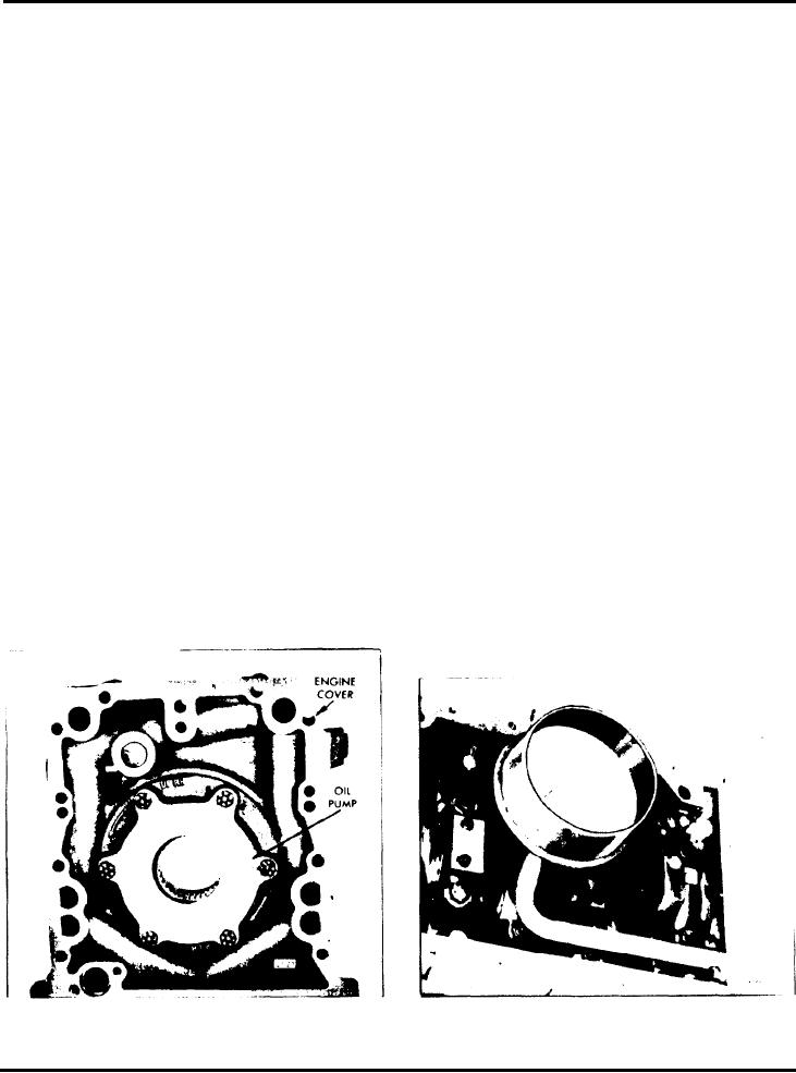
The lubricating oil pump. assembled to the inside of
the pump is then forced out under pressure through
the lower engine front cover as illustrated in Fig. 1, is
the discharge port into a passage in the front cover.
of the rotor type in which the inner rotor is driven by
which leads to the lubricating oil filter and cooler, and
d gear pressed on the front end of the crankshaft. The
is then distributed throughout the engine.
outer rotor IS driven by the inner rotor. The bore in
the pump body. in which the outer rotor revolves, is
If a check of the lubrication system indicates Improper
eccentric to the crankshaft and inner rotor. Since the
operation of the oil pump, remove and disassemble it
outer rotor has nine cavities and the inner rotor has
as outlined below.
eight lobes. the outer rotor revolves at eight-ninths
crankshaft speed. Only one lobe of the inner rotor is
in full engagement with the cavity of the outer rotor at
any given time. so the former can revolve inside the
Remove Oil Pump
latter without interference.
1. Drain the oil from the engine.
2. Remove the crankshaft pulley, fan pulley. support
By rotating the pump 180, it can be used for
bracket and any other accessories attached to the front
either a right-hand or left-hand rotation engine.
cover.
3. Remove the oil pan.
Operation
4. Refer to Fig. 2 and remove the four bolts which
attach the oil pump inlet pipe and screen assembly to
the main bearing cap and engine front cover or oil
As the rotors revolve, a vacuum is formed on the inlet
pump inlet elbow. Slide the flange and the seal ring on
side of the pump and oil is drawn from the crankcase,
the inlet pipe and remove the pipe and screen as an
through the oil pump inlet pipe and a passage in the
assembly. Remove the oil pump inlet elbow (if used)
front cover, IO the inlet port and then into the rotor
and gasket from the engine front cover.
compartment of the pump. Oil drawn into the cavities
5. Remove the lower engine front cover.
Fig. 1 - Typical Right-Hand Rotation
Fig. 2 - Typical Oil Pump Inlet Pipe and
Screen Mounting
Lubricating Oil Pump Mounting
SEC. 4.1 Page 1
July, 1972