DETROIT DIESEL 53
1.2.1 Valve Operating Mechanism
4. Prior to installing a new roller and pin, remove any
.010 " diametric clearance exists, replace the cam
burrs on the surfaces of the cam follower at the pin
follower assembly or install a new cam roller and pin,
holes.
which are serviced as a set. Be sure the follower legs
are beveled (Fig. 6) and check the total side clearance
5. Position the follower body in the groove of the
between the roller and follower; this clearance must
fixture with the proper size fixture plunger extending
not be less than ,015 " nor more than .023 ".
through the roller pin hole in one of the legs of the
follower body.
Oversize roller and pin sets are available for service
when required. However, DO NOT attempt to bore out
6. Position the roller in the cam follower body
the legs of a standard cam follower for an oversize
(Fig. 7). The small plunger in the tool will align the
roller and pin set. This cannot be over emphasized
roller with the pin holes in the follower body.
because of the extremely close manufacturing
tolerances.
7. Align the pin with the hole in the follower body and
carefully drive the pin into the body until the ends of
NOTE: Cam follower assemblies with the letter
the pin are centered in the legs of the body.
"S" stamped on the end of the roller, pin and
on one leg of the cam follower body are
8. Check the side clearance between the roller and the
equipped with oversize roller and pin sets.
follower body. This clearance must be .015 " to .023 ".
Remove and Install Cam Follower Roller and
Install Cam Follower and Push Rod Assembly
Pin
(Cylinder Head Removed from Engine)
1. Clamp fixture J 5840 securely in a vise as shown in
1. Install a serrated lower spring seat on each push
Fig. 7 and place the cam follower in the groove in the
rod. If the engine being assembled was equipped with
top of the fixture with the follower pin resting on top
plain lower spring seats, replace them with serrated
of the corresponding plunger in the fixture.
spring seats (Fig. 8).
2. Drive the pin from the roller with a suitable drift.
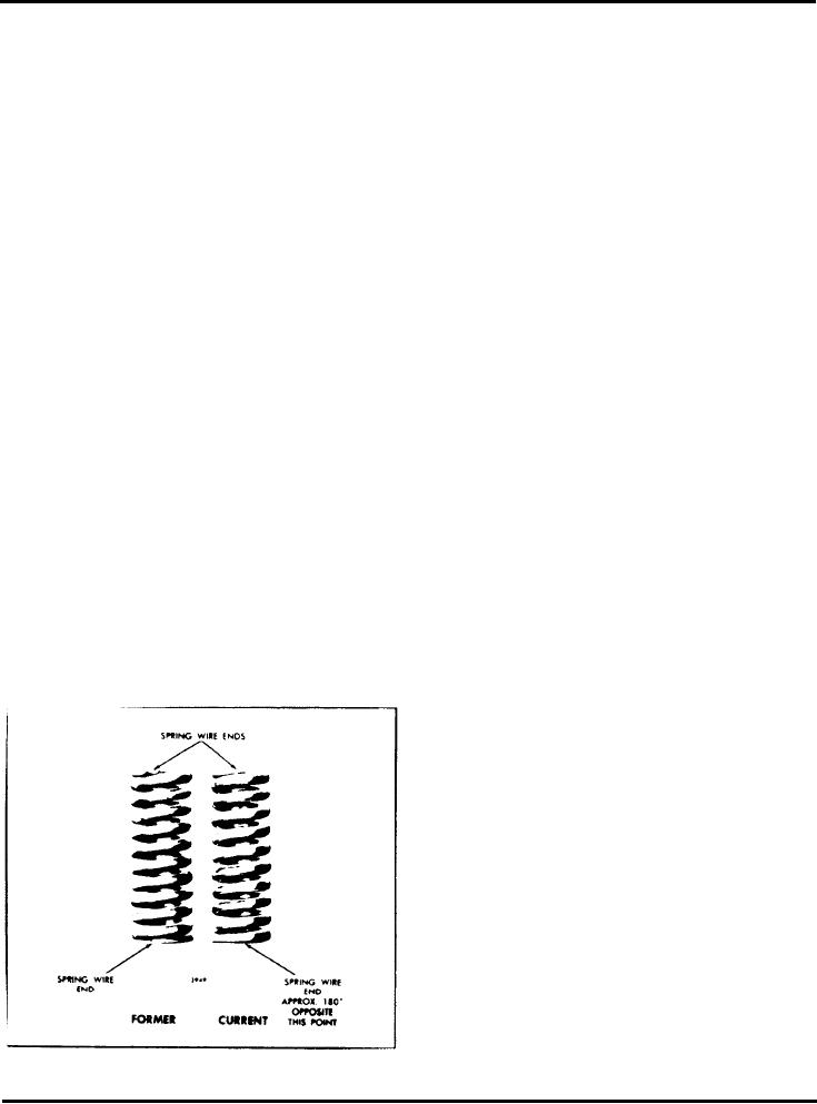
2. Place the push rod springs (Fig. 11) on the push
Exercise caution in removing the cam follower body
rods.
and roller from the fixture as the follower pin is seated
on top of a spring-loaded plunger in the fixture body.
3. Install the proper upper spring seat on each push
rod. The cup shaped spring seat used with the current
3. Before installing the new roller and pin kit, remove
type push rod spring may also be used with the former
spring.
the preservative by washing the parts with clean
lubricating oil or Cindol 1705. Do not use fuel oil.
4. Install the spring seat retainer in the cylinder head.
Then slide the push rod, lower spring seat, spring and
upper spring seat as an assembly into the cam follower
bore from the bottom of the cylinder head.
5. Screw the push rod lock nut down on the upper end
of the push rod as far as possible. Then screw the push
rod into the clevis until the end of the rod is flush with
or above the inner side of the clevis.
6. Immerse the cam follower assemblies in clean
Cindol 1705 (heated to 100o-125oF.) for at least one
hour before placing them in the cylinder head, to
ensure initial lubrication between the cam follower
roller pins and the roller bushings. Rotate the cam
follower roller during the soaking period to aid in
purging any air from the bushing-roller area. The
heated Cindol 1705 results in better penetration as it
is less viscous than engine oil and flows more easily
between the pin and roller bushing surfaces. After the
cam follower is removed from the Cindol 1705, the
cooling action of any trapped air in the pin and
Fig. 11 - Push Rod Spring ldentification
bushing area tends to pull the oil into the cavity.
Page 6

