
TM 5-3895-346-14
AXLE
DRIVE CARE AND MAINTENANCE
7. Check assembly for free rotation of differential gears and correct if necessary.
8. Install remaining bolts or capscrews, tighten to specified torque and thread with lock wire.
9. If bearings are to be replaced, press squarely and firmly on differential case halves.
DIFFERENTIAL BEARING PRELOAD AND GEAR LASH ADJUSTMENTS
On all hypoid-geared drive units the differential bearing preload and gear lash adjustments are obtained by the
use of hardened and ground spacers of the correct thickness located between the differential bearing cups and
the axle housing. On this type assembly, no shim pack is required between the pinion cage and axle housing.
Where spiral bevel gears are used, the housing is machined within limits which impose the correct differential
bearing preload and gear lash when the unit is assembled.
ADJUST DIFFERENTIAL BEARING PRELOAD
Hypoid-Splined Shaft
1. Remove thrust block using drift to drive pin out of cover.
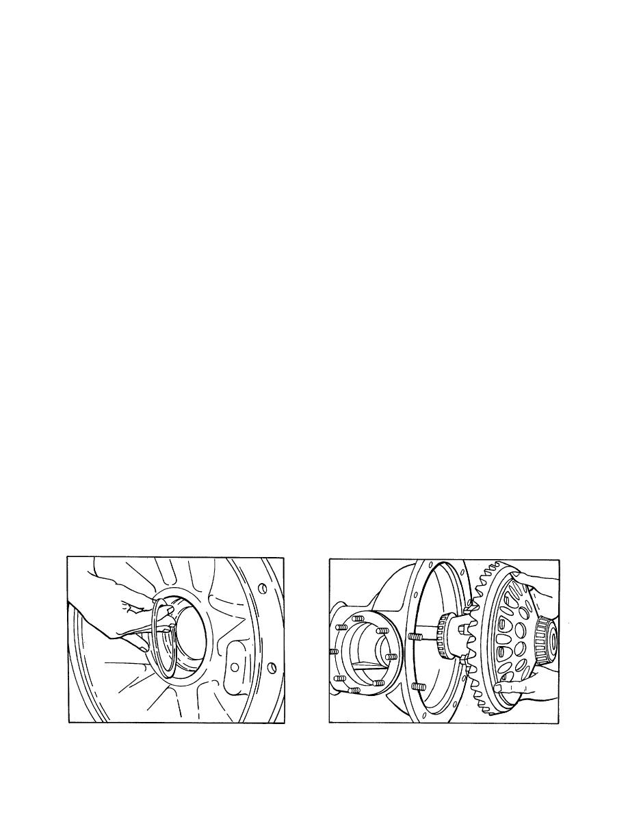
2. Install differential bearing spacers in the original positions if new bearing cups are installed (refer to Fig. 8).
NOTE
Spacers must be installed with the chamfered edge toward the machined surfaces in the housing.
3. Insert pipe used for disassembling through case half.
4. Position differential and gear assembly over pipe with gear facing the case half and slide into position (refer
to Fig. 9).
5. Install new gasket over case flange.
6. Position cover half over pipe and draw axle halves together with six bolts equally spaced.
7. Check differential and gear assembly end play with dial indicator through thrust block pinhole against gear
(refer to Fig. 10).
Figure 8.
Figure 9.
630
