TM 5-3895-346-14
HYDROSTATIC SYSTEM
PUMP REPAIR
Figure 18.
Figure 19.
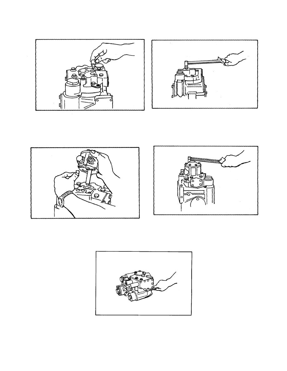
After assembly be certain these valves are below the surface of the end cap (refer to Fig. 19). Torque values
are specified at the end of this manual.
Figure 20.
Figure 21
When replacing the charge pump, align the gasket so that the small relief valve port is open and not blocked by
the gasket. Rotate the charge pump shaft so it aligns approximately with the slot in the end of the pump drive
shaft. Hold the idler spacer in place and install the charge pump onto the end cap. Rotate the charge pump
until the tang and slot engage and the pump is solidly on the end cap (refer to Fig. 20).
Figure 22.
Install the four hex capscrews and tighten (refer to Fig. 21).
Remove the hex capscrews and swing the control away from the pump housing. This area is sealed with both
O-rings and a gasket (refer to Fig. 22).
534


