
TM 5-3895-346-14
BLOWER DRIVE SUPPORT
ENGINE OVERHAUL
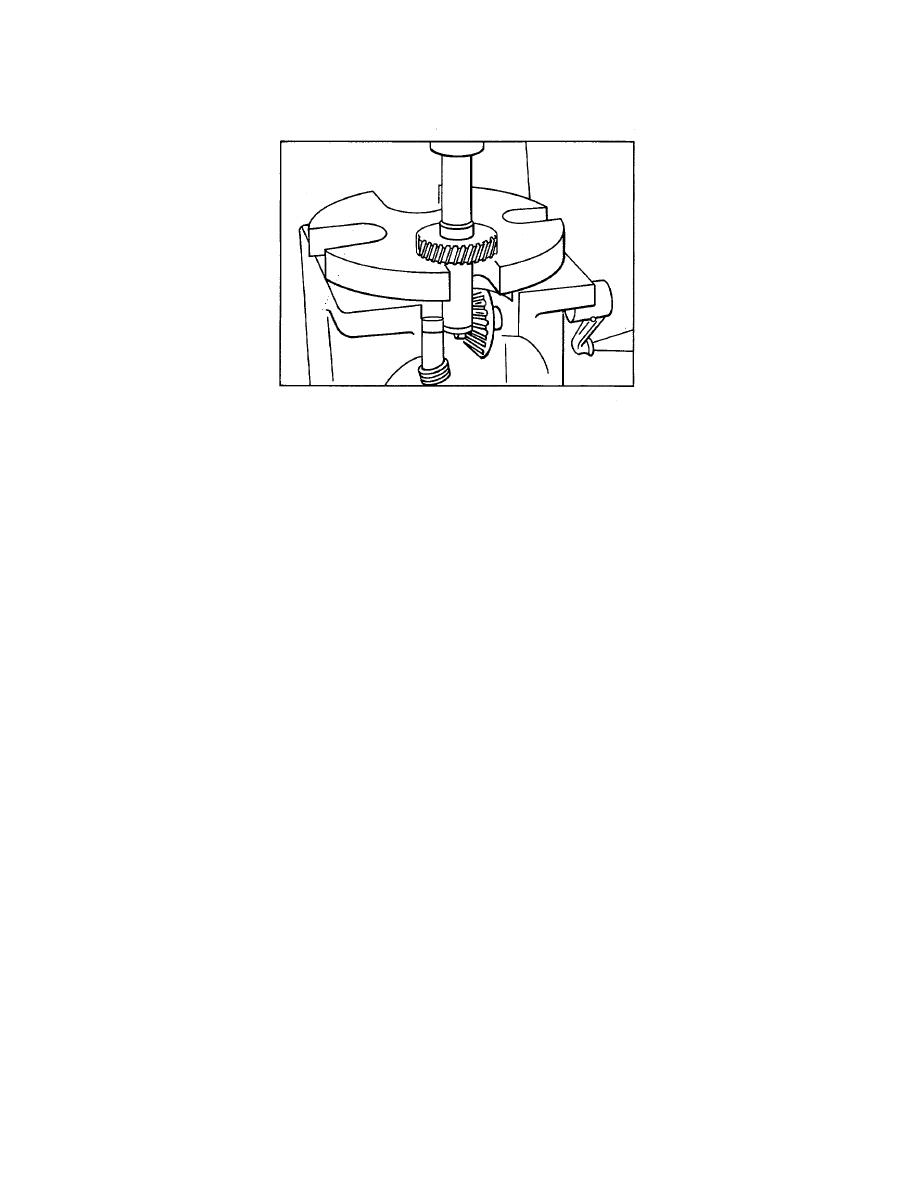
Figure 2. Pressing Blower Drive Gear From Shaft
Inspect the inside diameter and thrust surfaces of the blower drive gear support for scoring and wear. Also
check the outside diameter of the blower drive gear shaft for wear. The clearance between the shaft and the
support should not be less than 0.0035 inch (with new parts) or more than 0.007 inch (with used parts).
Inspect the serrations on the blower drive shaft and, if worn so that excessive backlash is felt when the shaft is
inserted into the blower drive gear shaft, install a new blower drive shaft.
Examine the blower drive support thrust washer for scoring and wear. Replace the thrust washer if
necessary. The thickness of a new blower drive support thrust washer is 0 093 to 0 103 inch.
Inspect the gear teeth for evidence of scoring, pitting, burning, or wear. If necessary, install a new gear.
Assemble Blower Drive Support
Refer to Fig. 3 for the relative position of the parts and assemble the blower drive support as follows:
1. Lubricate the blower drive gear shaft with clean engine oil and insert the shaft into the blower drive
support.
2. Assemble the thrust washer and the snapring on the shaft.
3. Install the key in the shaft, if it was removed.
4. Place the shaft and support in an arbor press.
5. Position the gear on the shaft so the keyway in the gear is in alignment with the key in the shaft. Then
place a sleeve on the gear and press the gear on the shaft until the clearance between the gear and support is
0.004 to 0.006 inch (Fig. 4).
Instail Blower Drive Support
1. Affix a new blower drive support gasket to the cylinder block rear end plate.
2. Install the blower drive support assembly by reversing the removal procedure.
3. Tighten the 3/8-24 support-to-end plate bolts (with copper washers) and the 3/8-16 support-to-flywheel
housing bolts (with plain washers and lockwashers) to 35 lb ft (47 Nm) torque.
190
