
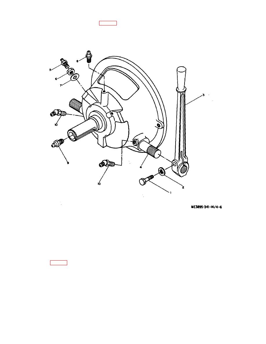
(2) Remove lube fitting 15), nut 16), and washer (7).
4-11. Operating Lever and Lube Fittings (fig. 4-6)
a. Removal.
(3) Remove remaining lube fittings (8), (9), and
(10).
(1) Remove bolt ( 1, washer (2), and remove lever
(3) from shaft (4).
b. Installation. Installation is in the reverse of removal.
1
Bolt
6
Nut
2
Washer
7
Washer
3
Lever
8
Lube Fitting
4
Shaft
9
Lube Fitting
5
Lube Fitting
10
Lube Fitting
Figure 4-6. Operating lever and lube fittings removal.
4-12. Drive Belt (fig. 4-7)
b. Removal.
a. Adjustment.
(1) Remove bolts (7) that secure cover plate (8) and
(1) Loosen engine base upper nuts (1).
remove cover plate.
(2) Tighten engine lower nuts 12) equally around so
(2) Remove bolts (9) that secure belt guard (10) and
that engine base (3) remains level.
remove guard.
(3) With fingers, squeeze belt (4) together, midway
(3) Loosen engine base lower nuts (2)
between pulleys (5) and (6). When the belt sides are
approximately 1/2 inch. This will allow engine base (3) to
approximately three inches apart, it is adjusted properly.
lower, and drive belt (4) to loosen. Disengage
4-10
