
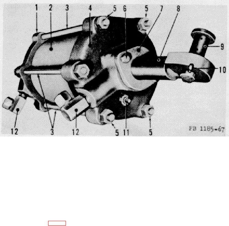
1
Cylinder swivel head
7
Gland
2
Cylinder
8
Piston rod
8
Cylinder stud
9
Piston rod pin
4
Cylinder gland seat head
10
Cotter pin
5
Stud nut
11
Pipe plug
6
Gland mounting screw
12
Adapter elbow
Figure 67. Hydraulic steering cylinder.
(2)
Make sure that the hollow of the V is toward the cylinder gland seat head (4).
(3)
Push the packing along the piston rod (8) until all sections are properly seated.
(4)
Attach the gland (7) to the cylinder gland seat head (4) and install the mounting screws (6).
(5)
Tighten the screws snugly but not too tight.
(6)
Operate the road roller and check the gland (7) for leaks.
154.
Hydraulic Oil Tank (fig. 68)
a. General. The hydraulic oil tank (3) stores the oil used for operating the hydraulic system. The tank is mounted on
four studs welded to the road roller frame, at the left side of the engine. The drain plug (7) is located on the bottom of the
tank (3) and is used to drain the hydraulic tank and system. A rubber hose (6) on the bottom of the tank connects the tank
(3) with the hydraulic oil pump. There are two hoses (2 and 9) on the top of the tank. The filler hose (9) is used for refilling
and the tank to valve hose (2) connects the tank with the operating valve. A pet cock (8) mounted on the side of the tank
is used to check the hydraulic oil level in the tank (3). b. Draining. Place a clean container under the tank (3) and remove
the pipe plug (7) on the bottom of the tank. Disconnect the
169