TM 5-3895-383-24
There is one intake and one exhaust valve for each cylinder.
Make reference to Valve System Components. The intake
valve opens when the piston moves down on the inlet stroke.
Compressed air from the inlet chamber is pulled into the
cylinder.
The intake valve closes and the piston starts to move up on the
compression stroke. When the piston is near the top of the
compression stroke, fuel is injected into the cylinder. The fuel
mixes with the air and combustion starts. The force of
combustion pushes the piston down on the power stoke.
When the piston moves up again it is on the exhaust stroke.
The exhaust valve opens and the exhaust gases are pushed
through the exhaust port into exhaust manifold (4). After the
piston makes the exhaust stroke, the exhaust valve doses and
the cycle (inlet, compression, power, exhaust) starts again.
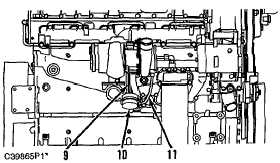
Exhaust gases from the exhaust manifold go into the turbine
side of the turbocharger (5) and cause turbine wheel (9) to
turn. The turbine wheel is connected to the shaft that drives
compressor wheel (8). The exhaust gases then go out the
exhaust outlet (10).
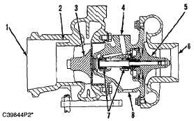
Turbocharger
Turbocharger Cross Section
(1) Exhaust outlet. (2) Exhaust bypass port. (3) Turbine
wheel. (4) Oil inlet port. (5) Compressor wheel. (6) Air inlet.
(7) Bearings. (8) Oil outlet port.
Waste Gate Turbocharger (if equipped)
(9) Actuating lever. (10) Case. (11) Line (boost pressure).
The turbocharger is mounted to the exhaust manifold of the
engine. All the exhaust gases go through the turbocharger.
The exhaust gases go into exhaust inlet of the turbine housing
and push the blades of turbine wheel (3). This causes the
turbine wheel and compressor wheel to turn at speeds up to
100 000 rpm.
Clean air from the air cleaner is pulled through the compressor
housing air inlet (6) by rotation of compressor wheel (5). The
action of the compressor wheel blades causes a compression
and heating of the inlet air. The hot compressed air from the
turbocharger is then cooled by the aftercooler before going to
the inlet manifold of the engine. This compression gives the
engine more power because it makes it possible for the engine
to burn additional fuel with greater efficiency.
Maximum rpm of the turbocharger is controlled by the fuel
setting, the high idle rpm setting and the height above sea level
at which the engine is operated.
When the engine is operating under low boost conditions a
spring pushes against a diaphragm in canister (10) and moves
actuating lever (9) to close the wastegate valve which will allow
the turbocharger to operate at maximum performance.
As the boost pressure increases against the diaphragm in
canister (10), the wastegate valve is opened and the rpm of the
turbocharger is limited by bypassing a portion of the exhaust
gases around the turbine wheel of the turbocharger.
NOTE:
The wastegate turbocharger is preset at the
factory and no adjustments can be made.
6-16