TM 5-3895-383-24
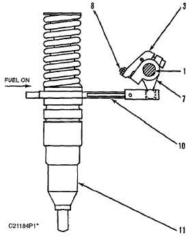
View AA From Injectors And Rack Control Linkage (Previous)
Illustration
(1) Shaft. (3) Clamp. (7) Lever assembly. (8) Synchronization
screw. (10) Rack. (11) Injector.
The rack control linkage connect the governor output to fuel
injector (11) at each cylinder. The governor output shaft is
pinned to link (4). Link (4) is connected to lever assembly (6).
When the governor demands more fuel, link (4) and lever
assembly (6) cause FUEL ON rotation of shaft (1) and clamps
(3). Each clamp then pushes lever assembly (7) as the shaft
rotates. Fuel Injector rack (10) is pulled by lever assembly (7),
allowing more fuel to be injected into the cylinder.
When the governor demands less fuel, link (4) causes shaft (1)
and clamps (3) to rotate in the FUEL OFF direction. Torsion
spring (2) then forces lever assembly (7) to also rotate
clockwise, pushing injector rack (10) toward shutoff. Torsion
spring (2), at each lever assembly (7), allows the rack control
linkage to go to shutoff, even if one injector rack is stuck open.
Power setting of the No. 1 cylinder injector is made with fuel
setting screw (5) in clamp assembly (9). As fuel setting screw
(5) is turned, shaft (1) rotates to a new position with respect to
link (4) and lever assembly (6). Adjusting screws (8) allow
synchronization of the injectors to the injector of No. 1 cylinder.
NOTICE
Do not loosen screws holding clamps (3) or clamp
assembly (9) to shaft (1). These screws are factory set to
the shaft (the screws can be identified as those with
socket heads filled with sealant). Loosening the clamps
will cause poor engine performance and may cause
damage to the engine.
Governor
The governor transfers the operator's requirements to the fuel
injector rack control linkage. The governor receives the
desired engine speed by the position of the throttle. The
governor output shaft immediately moves when the throttle is
moved. The motion of the governor output shaft then causes
the injector rack control linkage to rotate and move the injector
racks. As engine speed changes because of the rack change,
the governor adjusts the amount of fuel delivered. This causes
the engine to stabilize at the speed corresponding to the
throttle position. For further information refer to 3114, 3116 &
3126 Governor Service Manual, SENR6454.
6-13