
TM 5-3895-379-23-2
0260
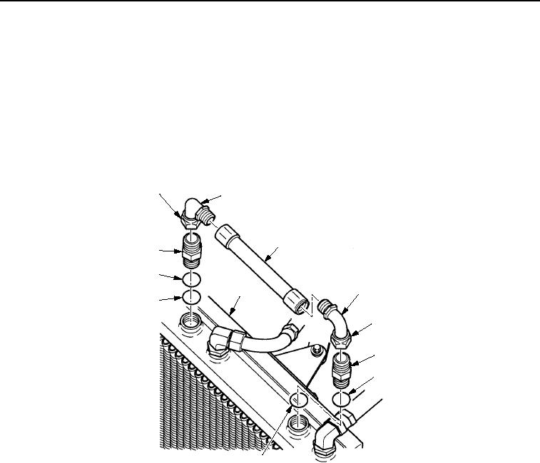
REMOVAL
1.
Loosen nut (Figure 1, Item 1) and remove elbow (Figure 1, Item 2) from connector (Figure 1, Item 9).
2.
Loosen nut (Figure 1, Item 1) and remove elbow (Figure 1, Item 2) from connector (Figure 1, Item 4).
3.
If damaged, remove hose assembly (Figure 1, Item 3) from two elbows (Figure 1, Item 2).
4.
Remove connector (Figure 1, Item 4), gasket (Figure 1, Item 5), and O-ring (Figure 1, Item 6) from hydraulic
oil cooler (Figure 1, Item 7). Discard gasket and O-ring.
5.
Remove connector (Figure 1, Item 9), gasket (Figure 1, Item 8), and O-ring (Figure 1, Item 6) from hydraulic
oil cooler (Figure 1, Item 7). Discard gasket and O-ring.
1
2
3
9
8
2
7
6
1
4
5
M0175SWR
6
Figure 1. Hydraulic Oil Cooler and Fan Shroud Removal.
NOTE
Tag and mark all hoses prior to removal.
6.
Loosen nut (Figure 2, Item 2) and remove hose (Figure 2, Item 3) from elbow (Figure 2, Item 1).
7.
Loosen nut (Figure 2, Item 5) and remove hose (Figure 2, Item 4) from elbow (Figure 2, Item 6).
03/15/2011Rel(1.8)root(maintwp)wpno(M00198)

