
TM 5-3895-379-23-2
0250
INTER-CIRCUIT RELIEF VALVE TEST
WARNING
Use caution when using the propel control lever. Roller may move when switching from
NEUTRAL to REVERSE.
1.
Place proper control lever in NEUTRAL (TM 5-3895-379-10).
2.
Place vibratory mode switch in auto (TM 5-3895-379-10).
3.
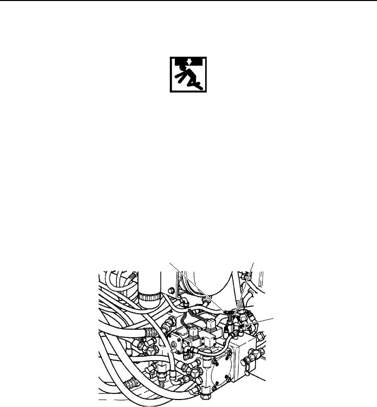
Connect pressure gauge to tap (Figure 3, Item 3).
4.
Start and run engine at HIGH idle (TM 5-3895-379-10).
5.
Place vibratory mode switch in dual drum vibration position (TM 5-3895-379-10).
6.
Place propel control lever in REVERSE (TM 5-3895-379-10). Pressure reading should be 3,350 +/- 100 psi
(23,100 kPa +/- 689 kPa).
7.
If pressure is not in range, inter circuit relief valve (Figure 3, Item 1) must be adjusted. To increase pressure,
turn adjustment screw (Figure 3, Item 2) counterclockwise. To decrease, turn adjustment screw
(Figure 3, Item 2) clockwise.
8.
Recheck pressure at tap (Figure 3, Item 3).
2
1
3
M1149SWR
Figure 3. Hydraulic Vibratory Test.
END OF TASK
03/15/2011Rel(1.8)root(maintwp)wpno(M00188)

