
The flow of oil developed by pump operation is controlled
by the integral flow control and relief valve.
NOTE Relief valve - an integral relief valve in the unit
protects the pump and other units in the hydraulic system
from excessive pressures. Relief valve adjustment - the
relief valve is pre-set at the factory and no field adjustment
should be made
If the relief valve setting must be
changed, a replacement valve should be installed
The flow control valve functions to bypass excess oil into
a return circuit through an internal passage in the pump
cover. The bypassed oil Is directed into the pump inlet.
The high velocity of this oil accelerates flow from the tank
This combination produces a super-charge at the inlet of
the pump.
When excessive pressure develops in the hydraulic
system, the relief valve unseats, causing the flow control
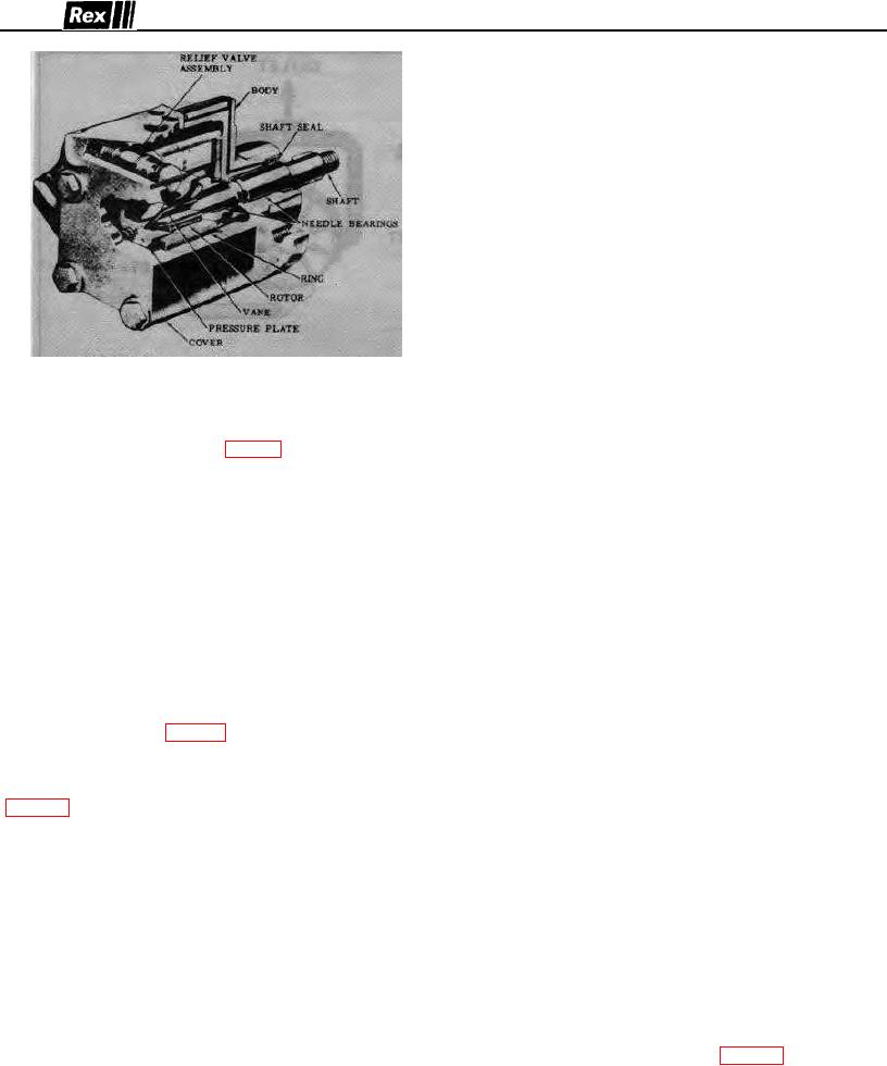
FIGURE 21
valve to open and bypass the entire pump output. This
VTM42 STEERING PUMP
limits maximum pressure in the system to the relief valve
setting and protects circuit components A portion of the
The assembly and construction of the VTM42 steering
oil bypassed under pressure relief conditions is returned to
pump is illustrated in cutaway Fig 21 The unit consists of
the reservoir to improve heat dissipation.
the body, cover, ring, rotor, vanes, pressure plate, relief
Normally, the pump requires no manual priming.
valve, and drive shaft assembly.
However, It is essential that, after starting a minimum
The pump is equipped with Integral flow control and relief
drive speed of 400 r p m. be held until the pump picks up
valves. Volume greater than the rated flow is by-passed
Its prime and pressure is built up in the system. Failure to
to the inlet, within the pump through action of the flow
observe the above precaution can result in scoring and
control valve which operates on a pressure differential The
possible seizure of the pump due to a lack of oil for
relief valve limits the maximum pressure m the hydraulic
lubrication.
circuit.
CAUTION: Do not use hydraulic brake fluid. Use only the
It is important that the hydraulic pump drive belt be
recommended oil.
maintained tight to prevent slipping to maintain maximum
For Trouble Chart refer to chart on page 26.
output of pump. The pump bracket is provided with
slotted holes by which the pump may be moved upward to
VTM42 PUMP OVERHAUL
tighten the drive belt.
A.
DISASSEMBLY - Before removing pump - be sure it
Operation - Reference Fig. 21, the rotor is driven within
is not under pressure.
the cartridge by a drive shaft, coupled to a power source.
1. A puller must be used to remove pulley from shaft,
As the rotor speed increases, centrifugal action causes the
otherwise bearing and shaft damage may result.
vanes to follow the cam-shaped contour of the pump ring
(Fig. 22) System pressure fed behind the vanes assures
During disassembly, special attention should be given
sealing contact of the vanes on the ring cam contour
to identification of parts for proper reassembly.
during normal operation.
Clean all parts except "O" ring seals in a clean
The ring is shaped so that two opposing pumping
mineral solvent. After drying thoroughly, lay the parts
chambers are formed, thus canceling any hydraulic loads
on a clean, lint free surface. All internal oil passages
on the bearings Radial movement of the vanes, and
of the pump cover, housing and body must be
rotation of the rotor, causes the chamber area between
thoroughly cleaned.
vanes to increase in size at the inlet (large diameter)
CAUTION Never use an air hose on or near the
section of the ring This results in a low pressure, or
exposed parts because of the presence of water and
vacuum in the chamber. This pressure differential causes
dirt In the air system.
oil to flow into the inlet, where it is trapped between the
All "0" rings, and the shaft seal should be replaced at
rotating vanes and is forced, through porting in the
reassembly. All seals should be soaked in hydraulic
pressure plate to discharge into the system as the
fluid before being used. Refer Fig. 23 and proceed
chamber size decreases at the pressure (small diameter)
with disassembly.
section of the ring.
19

