TM 5-3895-382-24
FLOAT Position
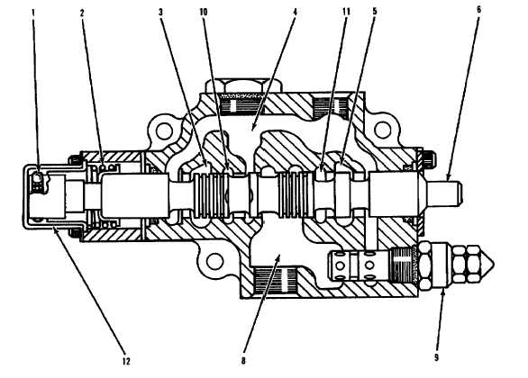
Leveling Blade Control Valve - Float Position.
(1) Detent ball and spring. (2) Centering spring. (3) Passage to rod end of cylinder. (4) Outlet passage. (5) Passage to head end of cylinder. (6)
Spool. (8) Inlet passage. (10) Passage. (11) Passage. (12) Detent sleeve.
When spool (6) is shifted from the HOLD position to the
FLOAT position the spool is moved all the way to the left.
Centering spring (2) is fully compressed, and detent bails and
springs (1) are located in the groove of detent sleeve (12).
Centering spring (2) does not have enough force to pull the
detent balls past the groove in the detent sleeve. Spool (6) will
be held in the FLOAT position until the operator moves the
blade control lever out of the FLOAT position.
With the control valve in the FLOAT position, spool (2) blocks
pressure oil in inlet passage (8) and internal passages (10) and
(11). Cylinder rod end passage (3) and cylinder head end
passage (5) are open to outlet passage (4). Since the cylinder
rod and head ends are open to tank, the blade will follow the
shape of the ground.
15-10