
DETROIT DIESEL 53
1.1
CYLINDER BLOCK
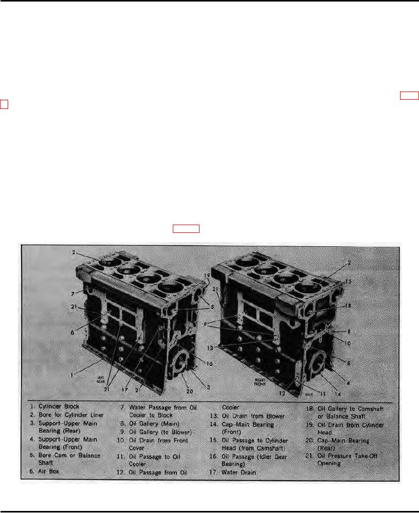
The cylinder block (Fig . 1) serves as the main structural part of the engine. Transverse webs provide rigidity and
strength and ensure alignment of the block bores and bearings under load. Cylinder blocks for the two, three and four
cylinder In-Line engines are identical in design and dimensions except for length.
The block is bored to receive replaceable wet-type cylinder liners. On the In-Line and 6V cast iron cylinder blocks, a
water jacket surrounds the upper half of each cylinder liner.
The water jacket and air box are sealed off by a seal ring compressed between the liner and a groove in the block (Fig.
An air box surrounding the lower half of the cylinder liners conducts the air from the blower to the air inlet ports in the
cylinder liners. An opening in the side of the block opposite the blower on the In-Line engines and air box openings in
both sides of the block on the V-type engines provide access to the air box and permit inspection of the pistons and
compression rings through the air inlet ports in the cylinder liners.
The camshaft and balance shaft bores are located on opposite sides near the top of the In-Line engine block.
The upper halves of the main bearing supports are cast integral with the block. The main bearing bores are line-bored
with the bearing caps in place to ensure longitudinal alignment. Drilled passages in the block carry the lubricating oil to all
moving parts of the engine, eliminating the need for external piping.
The top surface of the In-Line block is grooved to accommodate a block-to-head oil seal ring. Also, each water or oil hole
is counterbored to provide for individual seal rings (Fig. 6).
Fig. 1 - Cylinder Block (Four Cylinder Block Shown)
March, 1973
SEC. 1.1
Page 1