
b Removal.
(1) Turn the valve plug (1) counterclockwise and remove it from the cylinder block.
(2) Remove the adjusting washer (2) and pull out the valve spring (3) and valve (4).
c Installation.
(1) Install the valve spring (3) in the valve body (4).
(2) Install the valve spring (3) and valve (4) into the opening in the cylinder block.
(3) Install the adjusting washer (2) and valve plug (1). Tighten the valve plug.
d Adjustment. The oil pressure relief valve is adjusted by means of the adjusting washers (2). Install additional
washers to increase the opening pressure of the valve. Remove the washers to decrease the opening pressure of the
valve.
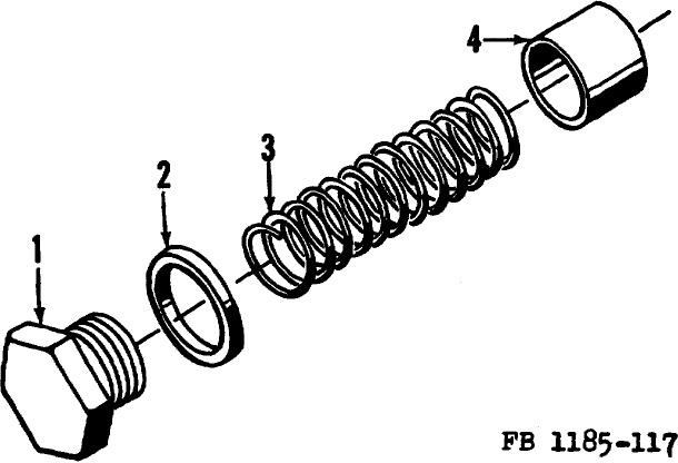
1 Valve plug
3 Valve spring
2 Adjusting washer
4 Valve
Figure 117. Oil pressure relief valve disassembled.
Section VIII. TRANSMISSION AND CLUTCHES
198.
Description
The heavy-duty transmission is enclosed in a machined case bolted to two welded cross-members of the road
roller frame. The transmission case also encloses the master clutch and bolts directly to the engine flywheel housing.
Transmission gears are machined of special alloy steel and heat treated. Forward and reverse movement of the roller is
accomplished through the use of a bevel pinion which is keyed
282