TM 5-3895-383-24
NOTICE
To avoid damage to the vibratory system during testing,
always perform the testing with the vibratory drum on top
of tires or on loose dirt. Tires will simulate a non-
compacted soil condition.
Never operate the vibratory system when the machine is
on concrete.
NOTICE
If a testing time longer than three (3) minutes is required,
rotate the drum periodically in order to lubricate the
eccentric weight shaft bearings.
NOTE:
The hydraulic oil temperature should be at least
38° C (100° F).
NOTE:
Two separate charge pressures are measured
during this test. The following procedure
measures the charge pressure after the charge
filter, when the propel control lever is in the STOP
position and when the vibratory system is OFF.
The second pressure measures the charge
pressure after the charge filter, when the propel
control lever is in the STOP position and when the
vibratory system is ON.
Vibratory System OFF
1.
Stop the machine and apply the parking brake.
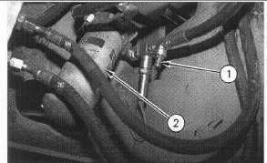
Illustration 44
Left Side of Machine
(1) Charge pressure test port. (2) Charge filter.
2.
Install a 4134 kPa (600 psi) pressure gauge at the
charge pressure test port (1) which is located after
vibratory charge filter (2).
3.
Install the multitach in order to measure the engine rpm.
4.
Install 4C-6500 Digital Thermometer into the hydraulic
oil tank.
5.
Start the machine and run the machine at high idle
(2350 ± 50 RPM) until the hydraulic oil temperature
reaches 38C (100F).
6.
Read the charge pressure at pressure test port (1).
Charge pressure (NEUTRAL) should be 2950 ± 150 kPa
(428 ± 22 psi).
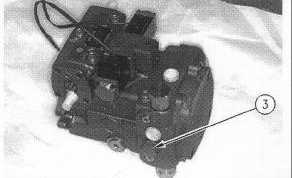
Illustration 45
Vibratory Pump
(3) Screw For The Adjustment Of The Charge Pressure.
7.
To increase the charge pressure in NEUTRAL, add
shims to the relief valve. Remove shims from the relief
valve in order to decrease the charge pressure.
NOTE:
Determine the condition of the charge filter before
any adjustments are made. This affects the
charge pressure. Nominal stack height of the
shims for the charge relief valve is 3.04 mm (.120
inch).
8.
Once Step 7 is complete, tighten the locknut to a torque
of 50 ± 5 N m (37 ± 4 lb-ft).
9.
Recheck the charge pressure. Once the vibratory
charge pressure is correct, proceed to "Vibratory
System ON".
11-46